 A robot can be defined as an electromechanical system with the capability of sensing its environment, manipulating it and acting according to the preprogrammed sequence. It is a machine that appears intelligent due to the instructions it receives from a computer inside it that handles multiple tasks. This article features a car robot-AT89C52-Based RoboCar—which uses a microcontroller to detect obstacles and manipulate its direction as per the inputs from three infrared (IR) sensors mounted in front of the car.
Basic components of RoboCar
The heart of the system is a microcontroller—Atmel AT89C52. It is programmed to accept inputs from its port p0 to sense the obstacles around it and control the steering to avoid any collision.
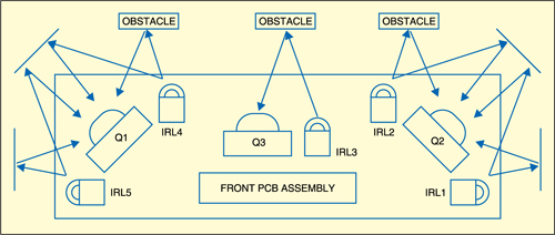
There are three TSOP1738 IR sensors (Q1, Q2 and Q3) used in this project—one at the centre and the remaining two on the left and right to detect obstructions, if any, in front of the RoboCar (Fig. 1). In case of an obstacle, or a potential collision, the microcontroller controls the steering through a bipolar stepper motor which is driven by an L293D motor driver IC. L293D is a quadruple half-H driver IC with an output current rating of 600mA at voltages ranging from 4.5V to 36V.
A DC motor is used for moving the car forward and backward, depending on the signals received from the three IR sensors. These sensors are used in any remotely-operated home appliance like TV, DVD player, etc. The IR sensor TSOP1738 operates at a frequency of 38 kHz. NE555 timer IC is used for generating a pulse of 38 kHz and transmitted through IR LEDs. There are five IR LEDs—two each on the left and right and one on the front of the robot. The reflected IR that beams from the obstacles are received by the sensors and sent to the microcontroller. The microcontroller is programmed in such a way that it takes the decision and changes the path of the robot as per the sensors’ inputs to avoid the obstacles.
Circuit description
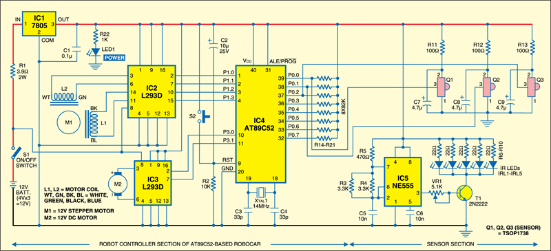
The schematic diagram of an AT89C52-based RoboCar is shown in Fig. 2. This RoboCar is powered by a 12V rechargeable battery connected to a 5V regulator IC 7805 (IC1) through a current limiter R1. This 5V is used for supplying power to the microcontroller AT89C52, IC NE555 and IR sensors TSOP1738.
 Switch S1 is used for turning on the circuit to run the robot. An additional filter circuit, comprising a resistor and a capacitor for each IR sensor, is used for preventing interference with noise signals. Switch S2 acts as a hardware reset for the microcontroller in case the robot is not running properly.
The microcontroller AT89C52 (IC4) is responsible for taking decisions if any obstacle is detected by the IR sensors. It drives the stepper motor (M1) so that the car changes track to avoid a collision with the obstacle.
Port 0 (P0.0 through P0.7) of the microcontroller is used as the input port that is connected to the sensors. Each of these port pins (P0.0 to P0.7) is pulled high through pull-up resistors R14-R21. Note that port pins P0.3 through P0.7 are not used in this application. You can use them to extend the application to make it a line following robot by using similar sensors and making some changes in the code. Port 1 (P1.0 through P1.3) is used for driving the stepper motor through the driver IC L293D (IC2) and port 3 (P3.0 and P3.1) is used for driving the DC motor (M2) for forward or backward motion through another L293D (IC3) driver IC.
Each sensor used here is a 3-pin modular device, where the first and second pins are negative and positive supply terminals respectively and the third pin is the output terminal. A filter circuit comprising a 100-ohm resistor and a 4.7µF capacitor is used for powering each sensor. Normally, the output of the sensor is high. When an IR pulse of frequency 38 khz falls on the IR sensor, its output goes low. This low output is sensed by Port 0 of the microcontroller and an action is taken as per preprogrammed instructions.
Pin 31 of the microcontroller has to be pulled high so that it can fetch the codes from its internal memory. But if any external memory is used in the circuit, the pin should be pulled low.
Here, R2 and C2 are used for the power-on reset function. As soon as the power is switched on, a high pulse is applied to pin 9 of the microcontroller to reset it. This action initiates the program and the RoboCar starts moving forward.
How a RoboCar works
As soon as the circuit is powered on, the controller IC4 fetches the codes from its internal memory and sets its pin 10 high and pin 11 low. This signal is fed to pin 2 and pin 7 of IC3, which drives the DC motor in one direction. This enables the car to move forward. IC5 is wired as an astable multivibrator to generate a 38kHz pulse.
The 38kHz pulses are amplified by transistor T1 to drive five IR LEDs. The IR sensors and LEDs are arranged in such a way that the output of the sensors is high where there is no obstacle near the car. But if there is any obstacle, the transmitted IR signals from the IR LED are reflected back from the obstacle that comes in the way. This makes the sensor output go low. This low output signal is fed to port 0 of the microcontroller. The output of sensor Q1 is connected to P0.0, Q2 to P0.1 and Q3 to port P0.2.
As soon as the output of the left sensor Q1 is pulled low to P0.0=0, the controller alters the spin of the DC motor, makes port P3=0 and stops the DC motor, thereby stopping the car for a moment. Then it drives port 1 in such a way that the stepper motor is rotated to the right, and the front steering wheels are also turned right, while the car continues to move forward. After a few seconds, the controller drives the stepper motor in the reverse direction (turning it left), which brings the steering wheels to the straight position and moves the car forward. Similar is the case when an obstacle is detected at the right sensor Q2.
In case there is an obstacle in the front, the centre sensor Q3 sends a low signal to port pin P0.2. This makes port P3=0 and the car stops. The steering wheels are turned left making port P3.0=0 and P3.1=1, which moves the car in backward direction with the steering still turned. After a few seconds, the DC motor is stopped by making port P3=0. The steering is set in the straight position and the car moves forward by making the port P3.0=1 and P3.1=0.
Thus, when the port P3.0=0 and P3.1=1, the car moves in the reverse direction; when P3.0=1 and P3.0=0, the car moves in the forward direction and when P3.0=0 and P3.1=0, the car stops.
Construction
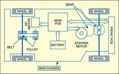
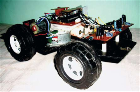
Fig. 3 shows the plan view of the mechanical model of the car. The rear wheel is driven by a belt, pulley and a DC motor. The pulley and drive belt for the rear wheels are taken from the HP Business Inkjet 1000 ink tank pump assembly.
If the polarity of the DC is reversed, the motor spins in the opposite direction. The same concept is used for driving the dc motor. The front wheels are mounted on a fibre gear which can be rotated in both directions using a gear and a stepper motor. The gears are taken from an old HP DeskJet 3325 paper-feed printer assembly and the stepper motor for steering control is taken from an old Epson Inkjet 460 printer assembly.
In order to avoid collision or friction between the main car chassis and the wheels, enough space has been provided between them for their free rotation. The front PCB is mounted at a height to avoid collision with front wheels while turning. Two gears are used for when the car is running on a rough surface. The main chassis is made of a thick fibre board.
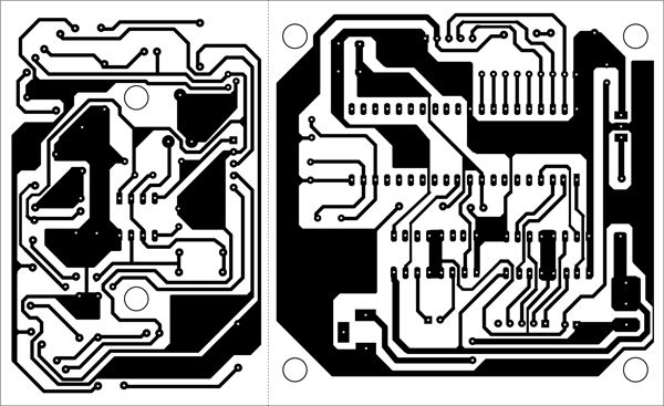
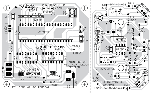
The circuit is assembled on a general-purpose PCB or on a PCB layout. The actual size, single-side PCB layout is shown in Fig. 4 and its component layout in Fig. 5.
The main PCB and the front PCB can be separated by cutting along the dotted line shown in the PCB layout.
The front PCB assembly is mounted on the front side of the robot as shown in Fig. 3. It is attached firmly on the main chassis board with nuts, bolts and spacers. The main PCB is also mounted on the chassis board with nuts and bolts and spacers. Three 4V rechargeable battery cells, taken from a laptop, can be placed between the main PCB and the chassis board (Fig. 6). The ‘charger input’ charging terminal has been provided in the PCB for charging the battery.
The main PCB and the front PCB are connected through CON1 and CON2 with suitable length of wires.
Software
The software code is written in C language using the free small device C compiler or SDCC. You can download SDCC from the link http://sourceforge. net/projects/sdcc/ files/, free of cost. The compiler creates some issues in Windows XP. In this project the code is compiled in a Windows 98 SE environment. The generated hex code is then burnt into the microcontroller unit (MCU) using a suitable Atmel 89 series programmer such as one from Sunrom Technologies or Frontline Electronics. You should not remove the microcontroller from the zero insertion force (ZIF) socket until the programming is complete.
Download source code: click here
Steps for installation
- Install SDCC using SDCC-2.9.0-setup file. It will automatically install under c:\Program files\SDCC
- Copy ‘Robo1.c’ file under C:\ program files\SDCC\Robocar
- Open the MSDOS prompt and give the above path
- Type ‘SDCC Robo1.c’ against the DOS prompt to compile it. If no errors are found in the code, it will generate the .lst and .ihx files in the same directory where the robo1.c file is located
- Convert the Robo1.ihx file to generate the robo1.hex file using ‘pack. ihx’ as:
packihx robo1.ihx>robo1.hex. - Use the robo1.hex file to program the MCU
Precaution
Once all the parts are assembled, it is necessary to check the operational function of the car on the repair bench itself before leaving it to move on the ground. You can lift the car, switch on the power and check the operation by putting your hand near the sensor to ensure each sensor is working perfectly. You can adjust the range of sensing by varying the preset VR1. It is not recommended to keep the range very long because this would cause the car to keep moving forward and backward as it senses any obstacle, even far away from it. Once you are sure that the car is operating well, you can leave it to move freely.


