


The basic problem with most of standard light sensors is that they require precise alignment of light beam to mute the circuit during standby mode. This automatic lighting fence circuit is so sensitive that it will detect a moving person at a distance of few metres in daylight or under electric lighting without cumbersome alignment of light beam.
It requires virtually no set up, and may be simply placed within the line-of-sight of almost any light source including ambient day light or fluorescent electric light. The beep generated from the circuit will be loud enough to detect the entry of a person in the room or the protected area being guarded.
Automatic Lighting Fence Circuit
The circuit uses a voltage comparator and a monostable timer to give the warning alarm on detecting a moving person. IC µA741 (IC1) is used as a voltage comparator with two potential dividers in its inverting and non-inverting inputs. Resistors R1 and R2 provide half-supply voltage of 4.5 volts to its inverting input (pin 2). LDR1 and preset VR1 form another potential divider to provide a variable voltage input to the non-inverting input (pin 3).

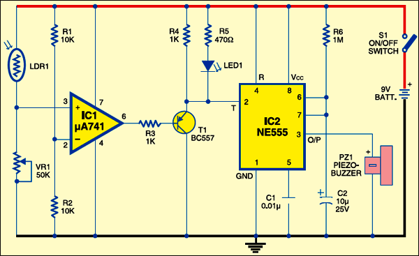
If VR1 is properly adjusted for the required light level, the output of IC1 will be high, which drives pnp transistor T1 out of conduction. This is due to the high potential at the base of T1. The emitter voltage of T1 will be high in this condition, which inhibits IC2 from oscillation and LED1 from lighting. IC2 is wired as a monostable timer. R6 and C2 provide a preset time delay.
As a person crosses the protected area, his shadow will be sensed by LDR1 due to change in the light intensity level and the voltage at the non-inverting input of IC1 will drop momentarily. The output of IC1 suddenly becomes low, allowing T1 to conduct. This triggers the monostable (IC2) and the alarm sounds.
Construction & testing
Assemble the circuit on a common PCB and house in a plastic case. Keep LDR1 inside a black tube to increase its sensitivity. Adjust preset VR1 until LED1 turns off at the particular light level. Keep LDR1 facing the entrance of the room or the area to be protected. Sensitivity of the circuit depends on the proper adjustment of VR1. If VR1 is correctly adjusted, the circuit can detect a moving person from a distance of about three metres.
The article was first published in June 2007 and has recently been updated.

Plz give detailed view about it sir
How can the LDR sensor detect object in the night time