


 This robot can be controlled with a smartphone using Bluetooth through an Android app. Its three sensors can measure four parameters: temperature, humidity, soil moisture, and ambient light intensity in greenhouses, farms, gardens, parks, etc.
Usually robots like robotic hand, agriculture robot, fire-fighting robot, spy robot, snake robot, humanoid, bomb (or mine) diffusing robot operate automatically without any human intervention or are remote-controlled. Remote-controlled robots are mostly wireless.
There are different types of wireless remote-controlled robots like:

- Fire-fighting robots, which are used as fire extinguishers for spraying water or cardon-dioxide on fire.
- Bomb (mine) diffusing robots, which are used to diffuse live bombs or mines in a battlefield.
- Snake robots, which can enter small tunnels or pipelines for search and rescue operations or to find out any problem like leakage in pipelines
This robot monitors the ambient parameters in a field. The operator can manoeuvre the robot in a radius of 10 to 30 metres and take measurements to select the best place for plantation. And if plantation is already done, the above-mentioned four parameters can be checked to see whether these are within the threshold levels or not for taking any corrective actions.
This project can be modified for some other applications also by just changing the sensors. For example, by equipping the robot with MQ2, MQ3 or similar gas sensors, it can be used to detect leakage of any gas like cardon-dioxide, methane, or LPG.
Working
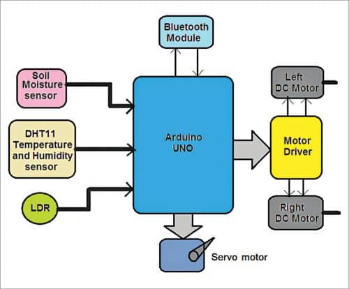
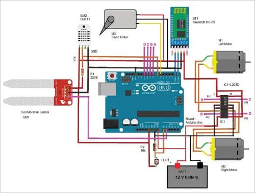
Before building the robot, let us first understand its working through the system block diagram shown in Fig. 1 and the circuit diagram in Fig. 2. The major building blocks of the system include the three sensors (soil moisture, DHT11 temperature and humidity sensor, and LDR), an Arduino Uno development board, Bluetooth module HC-05, DC servo motor, two DC gear motors, and motor driver chip L293D. Let us first understand the role of the major components used in the project.
Soil moisture sensor (SM1) is used to measure moisture content in soil and give analogue voltage output as per the moisture level. Its output voltage decreases as moisture content increases.
DHT11 temperature and humidity sensor (SM2) is a smart sensor that measures atmospheric temperature and humidity and gives direct digital values for temperature in °C and for humidity in % RH.
The light dependant resistor (LDR1) is a photo-conductive device whose resistance decreases as light intensity increases, and vice versa.
Bluetooth module (HC-05) is used to command (to move forward, reverse, left, and right) the robot from a smartphone with the help of Arduino Uno microcontroller.
The Arduino Uno board (Board1) performs following tasks:
- Reads analogue output voltage from soil moisture sensor and converts it into digital value. Then it calibrates it between 0 and 100% moisture level
- Reads temperature and humidity values from DHT11 sensor
- Reads analogue voltage output from LDR1 and calibrates light intensity between 0 and 100%
- Gets different commands from Bluetooth module and rotates two DC motors to move the robot forward, reverse, left, right, or stop it.
- Sends (transmits) readings of all three sensors to Android smartphone through Bluetooth module
Motor driver L293D (IC1) provides sufficient voltage and current to both the motors to rotate them. It amplifies the output of Arduino board (Board1) and drives the motors.
The DC motors (M1 and M2) drive left and right wheels of the robot and move it forward, backward, left, and right.
Soil moisture sensor (SM1) is attached to servo motor (M3) shaft. This motor moves the sensor up and down to insert it into the soil to check soil moisture content.
HC-05 module operates on 5V received from the Arduino board. It communicates with Arduino board with USART pins Tx (D1) – Rx (D0). So, its Tx pin is connected to Rx pin of Arduino board and vice versa.
DHT11 sensor also gets its 5V supply from Arduino board. Its digital output is connected to digital pin D7 of Arduino.
The analogue output of soil moisture sensor (SM1) is connected to analogue input pin A1 of Arduino board. Its 5V supply also comes from Arduino board.
LDR1 is configured in pulled-down mode with 10-kilo-ohm pull-down resistor. Its analogue output is given to analogue input pin A0 of Arduino board.
Digital pins D8, D9, D10, D11 of Arduino board drive DC motors M1 and M2 using L293D chip. These pins are connected to inputs of L293D, and two motors are connected to output of the chip. Servo motor signal (sig) input is connected to PWM output pin D6 of Arduino board. The motor gets 5V supply from Arduino board.
The motor supply pin Vss of L293D (pin 8) gets 12V from battery. The Arduino board also gets 12V input at its Vin pin from battery. That is, Vin pin gets 12V input and gives 5V output to all other components.
Circuit and operation
The circuit operation starts when 12V battery is connected to Arduino Uno board and L293D chip. Initially, both motors (M1 and M2) are at rest and so the robot is also at rest. The servo motor (M3) is at 0° position and soil moisture sensor is in upward position.
To move the robot in any direction, command is required from smartphone through Bluetooth based Android application, called Bluetooth Terminal HC-05 by mightyIT. To do this, open (start) Bluetooth Android application in smartphone and search for HC-05 Bluetooth module. Once the phone detects HC-05 module, pair it with the smartphone’s Bluetooth app. Enter passkey 1234 or 0000 the first time to pair with HC-05 module.
Now you can send commands from the smartphone to robot to move using the app. Following commands given in the table are used to move the robot (all these commands are already set in Android application):
When any of the above commands is sent (by sending the character in capital letter), it is received by HC-05 module. The module further gives this command to Arduino serially through its Tx-Rx pins. Arduino gets this command and compares it with set commands. If they match, the robot moves in the desired direction.
 Once robot is in motion, it keeps moving (within the range) until command ‘S’ is sent to stop it. When robot stops, it moves the servo motor by 90° so that soil moisture sensor can go down into the soil to capture soil moisture value. At the same time, it starts reading sensor values from DHT11 and LDR. It reads analogue voltage output from soil moisture sensor and LDR and converts it to the range of 0-100%. It also reads digital values of temperature and humidity from DHT11 sensor.
Robot transmits all four values of these sensors to the smartphone through Bluetooth module. It keeps transmitting these values every three seconds till it is stopped by pressing ‘S’ command. When any of the commands (F,B,R,L) is given, the corresponding servo motor moves from 90° to 0° and the soil moisture sensor moves up. The robot stops transmitting sensor readings and starts moving. Thus it gives an idea of ambient temperature, humidity, soil moisture, and light intensity in the area.
Operation of the circuit is controlled by the program embedded in Arduino Uno microcontroller ATMega328.
Software
The program code (BT_controlled_robot.ino) is written in Arduino programming language. It was tested using Arduino IDE version 1.8.18. Before compiling and uploading the code, make sure you include the relevant libraries, such as DHT_sensor_library-1.4.2 and DHT sensor library version 1.4.3. During testing it was found that without these libraries the code could not be compiled.
Download Source Code
Construction and testing
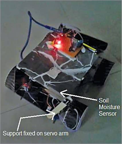
The circuit can be assembled on a breadboard or general-purpose PCB. The author’s prototype is shown in Fig. 3. On connecting the circuit to a 12V DC supply, the onboard LED on Bluetooth HC-05 will start blinking at a fast rate. When you pair it successfully with your Bluetooth app in your mobile phone, the LED will blink at a slower rate (two blinks per second). Open the Bluetooth Terminal HC-05 app from the mobile phone, select HC-05 again.
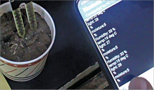
If everything’s fine, you can enter control commands (F,B,R,L) in the app to move the robot. On entering ‘S’ command, the robot will stop and all the sensor data can be seen on your mobile phone, as shown in Fig. 4.

Soil moisture sensor SM1 should be properly fixed to the servo arm/horn using either glue gun or screws. When servo motor pulls out soil moisture sensor from the soil, you can see the moisture level drastically reduces to 5, as shown in Fig. 5, indicating that the sensor is out of the soil.
Ashutosh M. Bhatt is M.Tech in embedded systems. Currently, he is lecturer of electronics and radio engineering at Government Polytechnic, Jamnagar, Gujarat