 Communication with remotely located automation systems is possible via the Internet. A physical communication port with a network is required for this communication. An Ethernet interface can be used for that purpose. Presented here is the design and implementation of an Ethernet interface for automation system, using a microcontroller.
Ethernet is quite a complex interface, which was difficult to use with small microcontrollers having little memory—until Microchip came up with ENC28J60 Ethernet chip. It is a small chip with only 28 pins that can be used as an Ethernet network interface for any microcontroller equipped with serial peripheral interface (SPI).
Therefore Microchip opens a whole new world of applications like the one we have implemented in this project where real-time readings of temperature and ambient light sensors placed at a remote place can be read using the Internet.
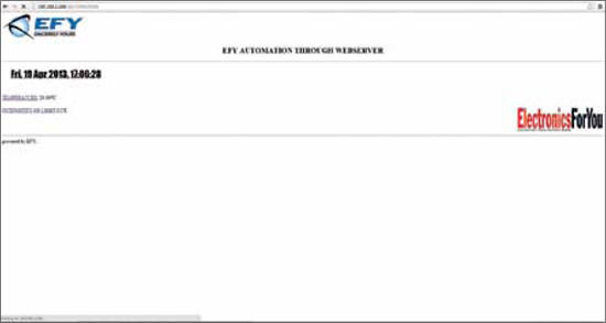
Fig. 1 shows the html page embedded in the source code of the automation system that provides these readings. The html page can be accessed from a remote location. Distance is no longer a limiting factor. Even Wi-Fi connectivity is possible because the devices can be connected to a wireless bridge too.
Circuit and working
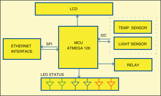
Fig. 2 shows the block diagram of the overall automation system. The temperature and light intensity are continuously monitored by two sensors that communicate with the microcontroller unit via I2C protocol. The relay is activated based on the readings from the ambient light sensor. Real-time reading from the sensors and the trigger status, for example the status of temperature, are continuously displayed on the LCD.

The automation system is connected to the router using Ethernet interface. The html page embedded in the code is continuously updated with real-time readings of both the sensors as shown in Fig. 1.
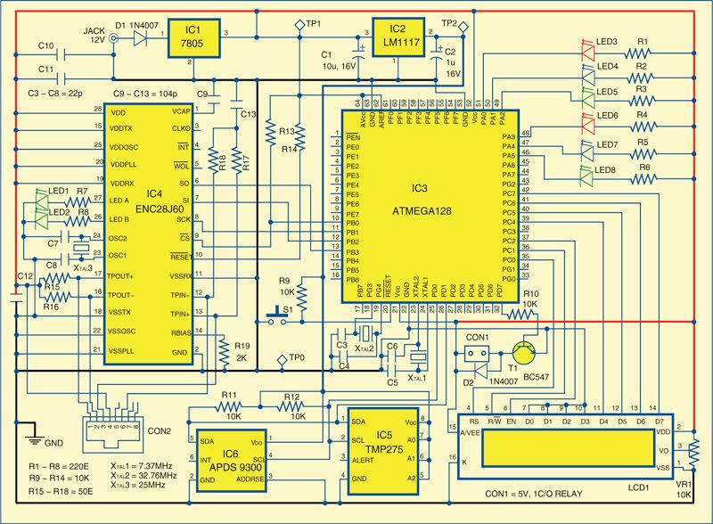
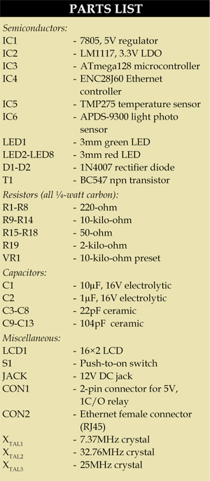
Fig. 3 shows the circuit built around microcontroller ATmega128 (IC3), Ethernet controller ENC28J60 (IC4), regulators 7805 and LM1117 (IC1 and IC2), digital-out temperature sensor TMP275 (IC5), miniature ambient light photo-sensor APDS9300 (IC6) and a few discrete components.
Ethernet interface. The ENC28J60 is a standalone Ethernet controller with an industry-standard SPI interface. It is designed to serve as an Ethernet network interface for any controller equipped with SPI. The ENC28J60 meets all the IEEE 802.3 specifications. It incorporates a number of packet filtering schemes to limit incoming packets. It also provides an internal DMA module for fast data through-put and hardware-assisted checksum calculation, which is used in various network protocols.

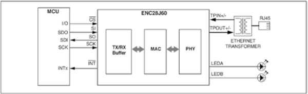
Communication with the host controller is implemented via SPI, with clock rates of up to 25 MHz. Two dedicated pins (LED A and LED B) are used for LED link and network activity indication. Fig. 4 shows the simplified connections scheme for easy understanding.
The SPI pins of IC3 are directly interfaced with IC4 as shown in Fig. 4. In the interconnection circuit there is no conversion required from 3.3 V to 5 V because the pins of IC4 are 5V tolerant.
Automation system. The heart of the system is ATmega128, which is an eight-bit microcontroller with 128 kB of in-system programmable Flash with read-while-write capabilities, 4kB EEPROM, 4kB SRAM, 53 general-purpose input/output (I/O) lines, 32 general-purpose working registers, real-time counter (RTC), four flexible timers/counters with compare modes and PWM, two US-ARTs, a byte-oriented two-wire serial interface, an eight-channel, 10-bit analogue-to-digital converter (ADC) with optional differential input stage with programmable gain, programmable watchdog timer with internal oscillator, an SPI serial port, IEEE 1149.1 standard-compliant JTAG test interface (also used for accessing the on-chip debug system and programming) and six software-selectable power-saving modes.
Microcontroller IC3 continuously monitors temperature and light intensity using sensors IC5 and IC6, respectively. Both the sensors communicate to the microcontroller via I2C protocol. Port pins PD0 and PD1 are used to interface both the sensors to the microcontroller. Real-time readings from both the sensors are displayed on LCD1, which is interfaced to IC3 using pins PC4 through PC7 for data pins of LCD1 and pins PC0 through PC2 for control pins of LCD1. Temperature range can be defned in the source code, within which LCD1 displays the message ‘it’s normal temperature’ and green LEDs (LED5 and LED8) glow. If temperature crosses the maximum of the range, the message on the display changes to ‘it’s too hot’ and red LEDs (LED3 and LED6) glow. In case temperature goes below the minimum limit, the message changes to ‘it’s too cold’ and blue LEDs (LED4 and LED7) glow.
The triggering value for light intensity can also be definedin the source code. If the intensity of light goes below the predefinedvalue, the relay connected through CON2 is driven by port pin PD7 of IC3 to switch on the bulb and the LCD shows the message ‘bulb on.’
The power to the whole system is provided using a 12V adaptor. Regulator IC1 provides a 5V output, which is further regulated by IC2 to 3.3 V.
Software
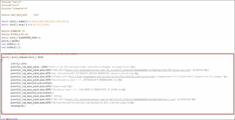
The program is written in ‘C’ language. It is compiled and programmed into the target device using WinAVR. The html page embedded in the source code can be accessed from a remote place to findout the readings of the temperature and light sensors. The section of the program definingthe html page is shown in Fig. 5.
To access the system, you have to change the mac address and IP address corresponding to your network arrangement in the line mentioned below in the source code:
[stextbox id=”grey”]static uint8_t mymac[6] = {0x54,0x90,
0x58,0x10,0x65,0x77};
static uint8_t myip[4] =
{192,168,2,248};[/stextbox]
The source code is compiled and programmed using WinAVR following the below mentioned steps:
1. Install WinAVR
2. Connect the programmer and check the COM port allotted to the device
3. Change the COM port in the make fileprovided together with the source code
4. Open command prompt and go to the directory where the program is saved
5. Type ‘make clean’ and press ‘enter’
6. Then type ‘make all’ and press ‘enter’
7. Finally, to program the microcontroller, type ‘make program’ after connecting the programmer to the target board
Download PCB and Component Layout PDFs: click here
Download Source Code: click here
Construction and testing
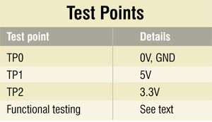
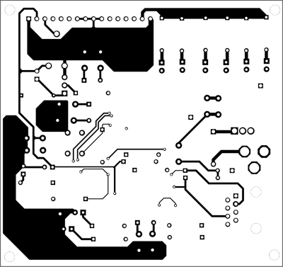
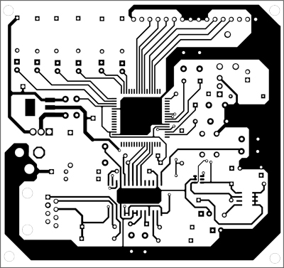
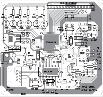
Both the layers of an actual-size, double-side PCB are shown in Figs 6 and 7 while the component layout is shown in Fig. 8. Assemble the circuit on a PCB as it saves time and minimises assembly errors. Carefully assemble the components and double-check for any overlooked error.For testing the circuit, refer the test-point table and verify the voltages. To test the functionality of the overall system, proceed as follows:
1. Connect the system to your computer using Ethernet cable
2. Give your system IP address 10.0.0.xx., where ‘xx’ should be less than 255
3. Click subnet mask. It will automatically change to 255.0.0.0
4. Change the IP in the source code, say, to 10.0.0.15 (different from the one provided to your computer)
5. Compile and burn the code in the target device
6. Open command prompt and ping 10.0.0.15. If it shows no packet lost, your computer is communicating to the automation system.
7. Now open any Internet browser and write 10.0.0.15 in the url tab. It opens the webpage that is embedded in the source code of the microcontroller with real-time readings from the temperature and light sensors.
The author is a B.Tech final year student of electronics and communication at Lovely Professional University