


 Light animations are visually appealing and hence widely used for advertising purposes. In this project, we present a MATLAB-based graphical user interface (GUI) approach to control the glowing pattern of a number of light-emitting diodes (LEDs). Use of GUI is advantageous since the user can control illumination patterns while performing other tasks in the PC.
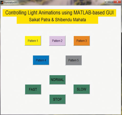
This project creates five different lighting patterns including ring counter and Johnson counter by clicking appropriate pushbuttons in the GUI. The blinking speed of LEDs can also be controlled using fast, normal and slow pushbuttons in the GUI. The author’s prototype is shown in Fig. 1 and the MATLAB-based GUI in Fig. 2.

Circuit and working of Light Animations Project
The circuit for controlling light animations using Arduino is shown in Fig. 3. It consists of an Arduino Uno board, eight LEDs and eight 1-kilo-ohm resistors.

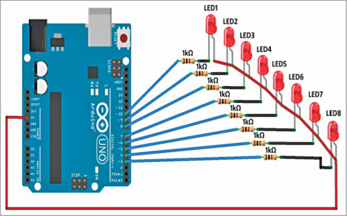
Arduino Uno is an AVR ATmega328P microcontroller based development board with six analogue input pins and 14 digital input/output (I/O) pins. The microcontroller has 32kB of ISP flash memory, 2kB RAM and 1kB EEPROM. The board provides serial communication via UART, SPI and I2C. The microcontroller can operate at a clock frequency of 16MHz. In this project, digital I/O pins 3 through 10 of the Arduino are configured as output pins and used to control the illumination of eight LEDs.
When a pushbutton corresponding to a particular pattern is pressed in the GUI, it executes the corresponding callback function in the source program (Illumination001.m.) The callback function executes program statements corresponding to that pattern and sends High or Low control signals to appropriate pins of the Arduino in order to create the desired glowing pattern. Eight series-connected 1-kilo-ohm resistors limit current flow through LEDs.
Software
We used Arduino IDE to program the Arduino Uno. The latest IDE can be downloaded for free from Arduino’s official website. After download, install the Arduino IDE and note the installation directory.
Download ‘Legacy MATLAB and Simulink Support for Arduino’ package from Mathworks website. Extract the compressed folder named ArduinoIO. From ArduinoIO folder, copy pde folder and paste it in C:\Program Files(or Program files x86)\Arduino\libraries. (The path may be different depending on the installation directory of the IDE). After pasting pde folder in the correct location, open Arduino IDE. If you have pasted the folder in the correct location, you can find pde in File->Examples->pde. Open the code by proceeding as follows: File->Examples->pde->adioes
Connect the Arduino Uno board to your PC. From Device Manager, note the COM port at which the Arduino Uno board is connected. From Tools menu in the Arduino IDE, select the board as Arduino Uno, and the COM Port number noted earlier. Upload adioes code to the Arduino Uno board by pressing Upload button in the IDE.
Now copy the entire content of the extracted ArduinoIO folder to a folder in My Documents (in Windows PC).
This GUI application program has been developed in R2014a version of MATLAB. After installing this MATLAB version in your PC, open the file install_arduino.m present in the directory where you copied contents of ArduinoIO folder. Now run the install_arduino.m file. This code will correctly install and save the path of the Arduino support package.
Open the source code file (Illumination001.m) for this project. Edit the line a=arduino(‘COM9’) with the COM port number in your PC where the Arduino Uno board has been connected. When you run the project file, MATLAB will try to communicate with the board. After successful communication is established, you can control LEDs by pressing the corresponding pushbuttons in the GUI.
Download source folder
Shibendu Mahata is M.Tech (gold medallist) in instrumentation and electronics engineering from Jadavpur University. Currently, he is pursuing Ph.D from NIT, Durgapur. He has keen interest in MCU-based real-time embedded signal processing and process control systems
Saikat Patra is passionate about electronics and MCU-based embedded system applications
Can you provide a demo video??
Please contact us on [email protected] for video or any other help