


Several intercom circuits have appeared in EFY using integrated circuits. The low-cost intercom circuit described here uses only three easily available transistors. Even a beginner can easily assemble it on a piece of veroboard.
Simple Intercom Circuit
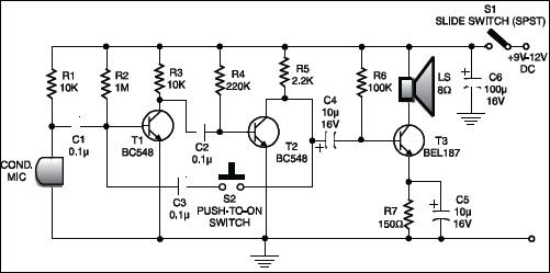
The circuit comprises a 3-stage resistor-capacitor coupled amplifier. When the ring button S2 is pressed, the amplifier circuit formed around transistors T1 and T2 gets converted into an asymmetrical astable multivibrator generating ring signals. These ring signals are amplified by transistor T3 to drive the speaker of earpiece.
The current consumption of this intercom is 10 to 15 mA only. Thus, a 9-volt PP3 battery would have a long life when used in this circuit.
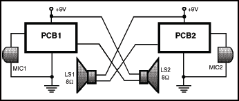
For making a two-way intercom, two identical units, as shown in the figure, are required to be used. The output of one amplifier unit goes to the speaker of the other unit, and vice versa. For single-battery operation, join the corresponding supply and ground terminals of both units together.
Construction and Testing
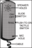
The complete circuit, along with microphone and earpiece, etc, can be housed inside the plastic body of a toy cellphone, which is easily available in the market. A suggested cellphone cabinet with the position of switches, speakers and microphone, etc. is shown.
Check the Video Tutorial Below:
The article was first published in January 2007 and has recently been updated.