LED-based moving-message displays are becoming popular for transmitting information to large groups of people quickly. These can be used indoors or outdoors. We can find such displays in areas like railway platforms, banks, public offices, hotels, training institutes, nightclubs and shops.
Compared to LEDs, liquid-crystal displays (LCDs) are easy to interface with a microcontroller for displaying information as these have many built-in functions. But these can’t be observed from a distance and large-size LCDs are very costly.
LED-based displays can be of two types: dot-matrix and segmental. If you implement a moving message display with multiplexed dot-matrix LEDs, it will be very costly for displaying 16 characters or more at a time. Moreover, programming will require a lot of data memory or program memory space. An external RAM may be needed to complement a microcontroller like AT89C51.
However, if you use alphanumeric (16-segment LED) displays for the above purpose, programming burden is reduced and also it becomes highly cost-effective. You can make your own display panel consisting of 16 alphanumeric characters at a much lower cost.
The circuit presented here uses 16 common-anode, single-digit, alphanumeric displays to show 16 characters at a time. Moreover, programming has been done to make the characters move in a beautiful manner. A message appears on the panel from the right side, stays for a few seconds when the first character reaches the leftmost place and then goes out from the left side.
It displays 16 different messages to depict different occasions, which can be selected by the user through a DIP switch.
Circuit description
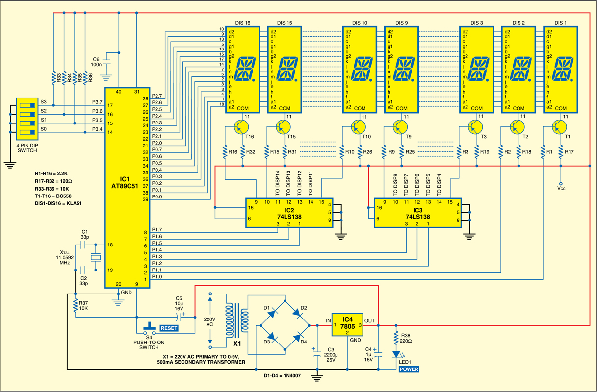
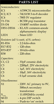
Fig.1 shows the circuit of the microcontroller-based moving-message display. It comprises microcontroller AT89C51, three-to-eight decoder 74LS138, common anode alphanumeric displays, regulator 7805 and a few discrete components.


At the heart of the moving-message display is Atmel AT89C51 microcontroller (IC1). It is a low-power, high-performance, 8-bit microcontroller with 4 kB of flash programmable and erasable read-only memory (PEROM) used as on-chip program memory, 128 bytes of RAM used as internal data memory, 32 individually programmable input/output (I/O) lines divided into four 8-bit ports, two 16-bit programmable timers/ counters, a five-vector two-level interrupt architecture, on-chip oscillator and clock circuitry.
Ports P0 and P2 of the microcontroller have been configured to act as a common data bus for all the 16 alphanumeric displays whose corresponding data pins have been tied together to make a common 16-bit data bus. Port-2 provides the higher byte of data, while port-0 provides the lower one to light up a character on the display. Port pins P1.2-P1.4 and P1.5-P1.7 of the microcontroller have been used as address inputs for decoder IC3 and IC4 (74LS138) to enable one of the fourteen alphanumeric
displays (DIS3 through DIS16) at a time, respectively. However, displays DIS1 and DIS2 are enabled or disabled directly by port pins P1.0 and P1.1. Pins 4 and 5 are grounded and pin 6 is made high to enable decoder 74LS138.
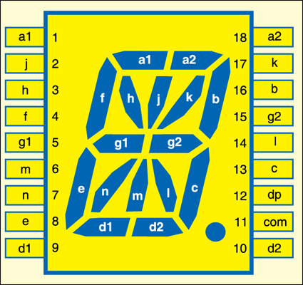
Fig.2 shows the pin configuration of the common-anode alphanumeric display.

All the corresponding data pins Dis 1 through DIS16 of alphanumeric displays have been tied together, while the common anode of each display is separately powered via a BC558 transistor which switches ‘on’ or ‘off’ as required, through outputs of 74LS138 ICs and pins P1.0 and P1.1 of IC1. The higher nibble of port P3 (P3.4 through P3.7) is used as a selection bus to select one of the 16 previously stored messages using the 4-bit binary value present on these pins. This value can be changed through a 4-pin DIP switch (S0 through S3).
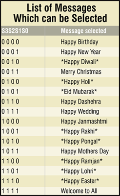
Selection pins P3.4 through P3.7 are pulled high via resistors R36 through R33, respectively. When the switch connected to a given pin is open the value is high (1), and when it is closed the pin is held low and the value becomes ‘0.’ In this way, by using a 4-bit number you can select any of the 16 messages shown in the Table.

Capacitor C5 and resistor R37 form the power-‘on’ reset circuit, while a push-to-connect switch has been used for manual reset. An 11.0592MHz crystal generates the basic clock frequency for the microcontroller. To change the message being displayed while the circuit is working, first change the number present at the selection bus, then press ‘reset’ key.
The 220V AC mains is stepped down by transformer X1 to deliver the secondary output of 9V, 500 mA. The output of the transformer is rectified by a full-wave bridge rectifier comprising diodes D1 through D4, filtered by capacitor C3 and then regulated by IC 7805 (IC4). Capacitor C4 bypasses any ripple present in the regulated power supply. LED1 acts as the power-‘on’ indicator.
Construction
Fig.3(View as PDF) shows an actual-size, single side PCB layout for the microcontroller-based moving-message display circuit, except displays DIS1 through DIS16, transistors T1 through T16 and resistors R17 through R32. Component layout for this PCB is shown in Fig.4(View as PDF).
Download PCB and component layout PDFs: click here
Fig.5 shows the PCB for displays DIS1 through DIS8, transistors T1 through T8 and resistors R17 through R24. Component layout for this PCB is shown in Fig.6. You need to use an additional PCB as shown in Fig. 5 for DIS9 through DIS16, so as to configure 16 alphanumeric displays. For this PCB, the corresponding components will be transistors T9 through T16 and resistors R25 through R32 in addition to displays DIS9 through DIS16. Corresponding connector are provided to make a proper connection. Connectors CON2, CON4 and CON6 of Fig.3 are connected to CON2, CON4 and CON6 of Fig.5, respectively, through external wires to interface DIS1 through DIS9. Connectors CON3, CON5 and CON7 of Fig.3 are connected to CON2, CON4 and CON6 of Fig.5, respectively,through external cable to interface DIS9 through DIS16.
Software and its working
The source code ‘movmsg.asm’ is written in Assembly language and assembled using cross-compiler. It is well commented and easy to understand. Timer 1 has been used to generate a delay of around 1 ms for the switching gap between two consecutive displays. Thus, each display is enabled for 1 ms while displaying a message. The length of this cycle depends upon the length of the message string. The cycle repeats after a ‘0’ is encountered at the end of each message stored in the look-up table at the end of the program.
Each time, to display a character at a given display, first two bytes (16 bits) of data are sent to Port-2 and Port-0, then the desired display is enabled by sending its address to Port-1. Thereafter a delay of 1 ms (slightly more than that) is generated by timer 1. Upon timer overflow, the entire display panel is refreshed by passing ‘FFFFH’ to the data bus. Then the next character at the next display is passed in the similar manner. The cycle frequency is variable (depending upon the length of the message) but always high enough so that the message appears continuous to the human eye.
Timer 0, with its interrupt enabled, is used to change the starting address of the message in cyclic manner so that the characters scroll from left to right with a proper gap between each shift. Meanwhile, the interrupt service sub-routine also checks for the starting address of DIS16 (right-most display). As soon as the first character reaches DIS16, the message stays for a longer time so that the entire message (message length not longer than 16 characters) can be easily read. Thereafter, characters again start scrolling rightwards, so the entire message goes out and disappears after a while to reappear from left side.
All the messages are stored in the form of a look-up table in the program memory (ROM) itself. When the circuit is switched ‘on’ (or reset), the monitoring program first checks for the binary number present at the selection bus and according to that, the ROM address of the starting character of the selected message is loaded into the data-pointer. Thereafter, on-chip ROM reading is used to read the entire message over there.
Note that each character is represented in the look-up table of the source code by two bytes. For example ‘S’ is represented by ‘Sh’ and ‘Sl’ separated by a comma. In addition to the alphabets, Arabic numerals and a few special characters have been defined in the program. For instance, a blank space is represented by ‘bsh, bsl.’ Thus, it is very easy to modify the program.
Suppose you want to display “HOUSE NO 401-H” in place of message ‘0.’ First, open the source code in the editor. Delete the old string and write the new string as below:

(Please note that the assembler is case-insensitive. Still, upper and lower cases have been used for clarity.)
Future enhancements
Many more messages would be possible if complete Port-3 is used for message selection. Pins RxD, TxD, INT0 and INT1 have been kept free, so that these can be used for interfacing with the serial port of the PC. Also, interrupt pins can be used to display some message and sound an alarm in the case of an emergency. For example, a fire sensor can be connected to ‘INT0’ and a vibration detector to ‘INT1.’ These pins can also be used to send signals to synchronise a similar system that displays another related message at the same time, so a 16-character, two-line display is made possible.
Download the source code and other relevant files: click here


i want this programme
It is present on the page itself for download.
there isnt any program found on page
plz send it may email id
my email id is [email protected]
PLZ SEND IT IMIDETLY when u check your id
You can download it from this link: http://www.efymag.com/admin/issuepdf/Microcontroller-Based%20Message%20Display%20System.zip
i dont find its program at here
You can download it from this link: http://www.efymag.com/admin/issuepdf/Microcontroller-Based%20Message%20Display%20System.zip
Please,can you send me embeded c code of 89c51 based msg display on my gmail
You can download it from this link: http://www.efymag.com/admin/issuepdf/Microcontroller-Based%20Message%20Display%20System.zip
Hi can I get complete report of this project.Can u pls send it to [email protected]
Hi Praneet Rane, all the required information is already present within the article.
Hi Can I get the full project . I need the coding part. which compiler used. Please send it to mail
[email protected]