


Protect your mobile phone from unauthorised use or theft using this simple mobile theft alarm circuit. It can generate a loud chirping sound when somebody attempts to take away the mobile handset. The added feature is that the circuit also works as a mobile charger.
Mobile theft alarm circuit
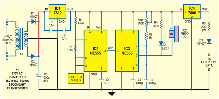
The circuit is powered by a step-down transformer X1 with rectifier diodes D1 and D2 and filter capacitor C1. Regulator IC 7812 (IC1) along with noise filter capacitors C2 and C3 provides regulated power supply.
The circuit utilises two NE555 timer ICs: One as a simple astable multivibrator (IC2) and the second as a monostable (IC3). The astable multivibrator has timing resistors R1 and R2 but no timing capacitor as it works with stray capacitance. Its pins 6 and 2 are directly connected to a protecting shield made up of 10cmX10cm copper-clad board.

The inherent stray capacitance of the circuit is sufficient to given an output frequency of about 25 kHz with R1 and R2. This arrangement provides greater sensitivity and enables the circuit with hand capacitance effect. Output pulses from the oscillator are directly given to trigger pin 2 of the monostable. The monostable uses a low-value capacitor C6, resistors R3 and preset VR1 for timing.
Circuit operation
The output frequency of the monostable is adjusted using preset VR1 such that it is slightly less than that of the astable. This makes the circuit standby, when there is no hand capacitance present. So in the standby mode, the astable’s output will be low. This makes the trigger input of monostable low and output high.
The warning LED1 and buzzer are connected such that they become active only when the output of the monostable sinks current. In the standby state, the LED1 remains ‘off’ and the buzzer is silent. As somebody tries to take the mobile phone from the protecting shield, his hand comes near the shield or makes contact with the shield, which introduces hand capacitance in the circuit. As a result, the astable’s frequency changes, which makes the trigger pin of the monostable low and its output oscillates. This produces chirping sound from the buzzer and also makes the LED1 blink.
The circuit can also be used as a mobile charger. It provides output of 6V at 180 mA through regulator IC 7806 (IC4) and resistor R5 for charging the mobile phone. Diode D3 protects the output from polarity reversal.
Construction & testing
This mobile theft alarm circuit can be wired on a common PCB. Enclose it in a suitable case with provision for charger output leads. Make the protective shield using 10cmX10cm copper-clad board or aluminium sheet. Connect it to the circuit using a 15cm plastic wire. Leads of all capacitors should be short.
Adjust VR1 slowly using a plastic screwdriver until the buzzer stops sounding. Bring the hand close to the shield and adjust VR1 until the buzzer sounds. With trial-and-error procedure, set it for the maximum sensitivity such that as soon the hand comes near the shield, the buzzer starts chirpring and the LED blinks. Instead of using the copper cladding for shield, a metallic mobile phone holder can be used as the shield.
The article was first published in September 2007 and has recently been updated.
