 Radio detection and ranging (radar) systems detect the presence and distance of objects using radio frequencies. The distance of an obstacle is calculated from the time taken for the radio waves to travel to the object and, after reflection from it, return back. Light detection and ranging (lidar) systems work much the same way; the only difference is they use laser light instead of radio waves.
This simple and affordable project uses the concept of finding an object using a lidar module. The VL53L0X lidar sensor module used here is available as a breakout board.
The lidar module sends laser pulses and calculates the distance of an object from it using the time of flight. It oscillates to find the obstacle within its range and displays the same on a graphic liquid crystal display (GLCD).

Circuit and description
The circuit diagram for object detection using lidar is shown in Fig. 1. The GLCD screen used here has 128×64-pixel resolution and is divided into two equal halves of 64×64 pixels. By changing CS1 (pin 15) and CS2 (pin 16) pins of GLCD, the left and right parts of the screen are activated to display the data. The data and command are of 8-bit length (one byte) and differentiated by selecting status of RS pin. Preset VR1 is used to adjust GLCD screen’s contrast.
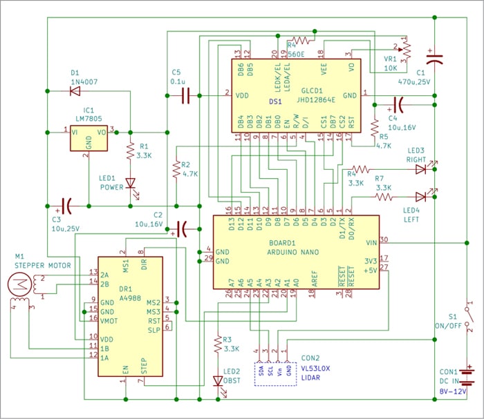
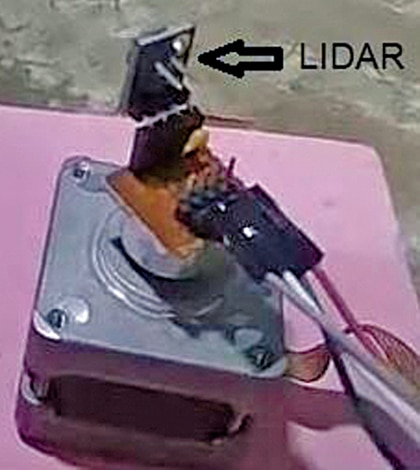
The lidar module is fitted on the shaft of a stepper motor (see Fig. 2). The selected stepper motor has small NEMA17 frame size with 1.8-degree step and 1A coil current rating, or as per individual choice. The selected stepper motor driver module A4988 can deliver up to 2A current to the stepper motor.
The brain of the system is compact, breadboard-compatible Arduino Nano board, which uses surface mount ATmega328 as its microcontroller. The Arduino Nano board can be placed on the PCB or breadboard using Berg strips quite comfortably.
Setup and usage
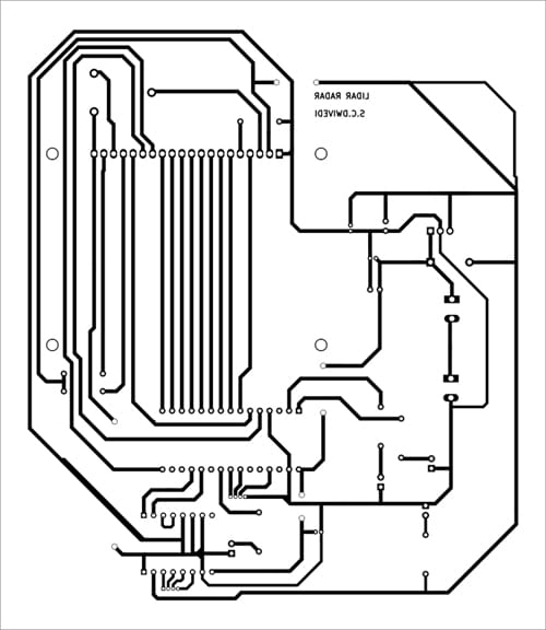
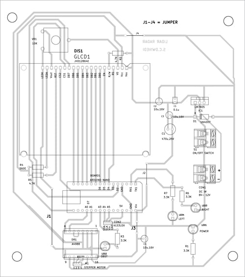
Upload the sketch to Arduino Nano and connect all the components as shown in the circuit diagram. Attach the lidar module to the stepper motor shaft with the lidar sensor facing towards the object. The solder-side PCB layout of obstacle detection using Lidar module is shown in Fig. 4 and its component layout in Fig. 5.
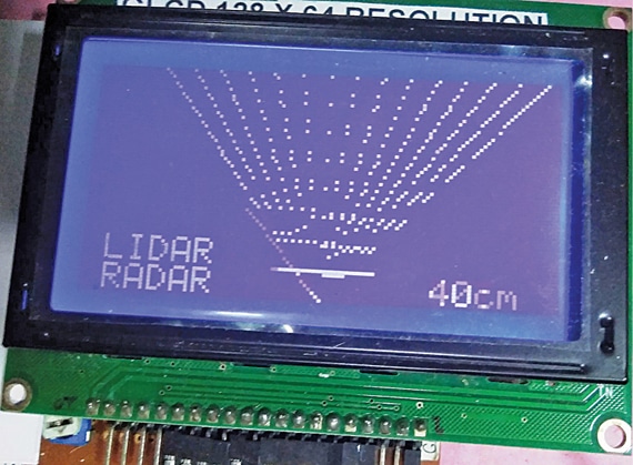
When the power supply to the circuit is switched on through switch S1, the display shows ‘LIDAR RADAR’ and the stepper motor rotates to its starting position. Then the stepper motor shaft rotates right and left (within 60 degrees) along with the lidar module attached to it to detect the object.
On detection, the distance of the object is read by Arduino Nano in centimetres (cm) and displayed on the GLCD screen. If the distance is more than 99cm, the display shows ‘OUT’ to indicate that the object is out of range. The object detected by the lidar at 40cm distance, along with the light rays, is shown in Fig. 3.
There are four LED indicators in the circuit. LED1 is the power indicator while LED2 (OBST) indicates that there is an object within the 99cm range at every movement. LED3 (LEFT) and LED4 (RIGHT) indicate whether the object is on the left side or right side of the area being scanned. If the object is in the middle, both LED3 and LED4 glow.
 The following points regarding this system are worth noting:
- The lidar may not detect transparent obstacles as it works on the reflection of light.
- To change the direction of stepper motor rotation, just reverse the connections of stepper motor to A4988 driver.
- The current limiting of stepper motor may be controlled by adjusting the preset on A4988 module (refer A4988 module data sheet), if required.
- The following variables may be modified in the sketch (then uploaded) to match individual need, if any:
Before compiling and uploading the code to Arduino Nano, you need following files, which can be downloaded from Link.
VL53L0X.cpp VL53L0X.h GLCDfont.h license.txt
This circuit is useful for an obstacle-detection robotics project to know the distance of the obstacle.
Download PCB and Component Layout PDFs: click here
Download Source Code
Related Object tracking and Detection projects: 3D Object Tracking and Recognition AI-powered Object Detection Object Tracking Camera using Raspberry Pi and MediaPipe Object-detection using IR SensorFayaz Hassan is Manager at Visakhapatnam Steel Plant, Visakhapatnam, Andhra Pradesh. His interests include MCU projects, mechatronics, and robotics