


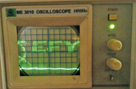
 Cathode ray oscilloscope (CRO) is a versatile laboratory instrument which is used to display, measure and analyse electrical signals. It is nothing but a fast x-y plotter that displays an input signal versus another signal or time. There is a luminous spot that moves over the display area in response to the input voltage. But displaying a monochrome bitmap image on an oscilloscope is a challenging yet interesting task. Here we present a project where you can display any image or multiple images (monochrome) on an analogue oscilloscope. Fig. 1 shows an‘ EFY’ image on the oscilloscope.
Circuit and working
The heart of the project is ATmega16 microcontroller—a low-power CMOS 8-bit chip based on AVR enhanced RISC architecture. It has 16kB in-system programmable Flash memory, 512 bytes of EEPROM and 1kB SRAM. A 16MHz crystal is connected across its pins 12 and 13 to provide basic clock. An R-2R ladder network DAC (digital-to-analogue converter) is used to convert digital (8-bit) values from the microcontroller to analogue values that are input to the oscilloscope.
Software
The software is written in C language and compiled using Programmer’s Notepad of WinAVR software. The hex code is burnt in the microcontroller using a suitable programmer. The fuse settings for ATmega16 are:
lfuse-0xef
hfuse-0x99
The code is written such that it accepts byte codes in pages and columns format. The byte codes of the image is in the intel[] array which is stored in Flash memory. The myte[] array stores the pixel data of 32 pixels along a column, indicating the on/off states. On state is represented by a value of 1 to 31 and an off state by 0. The vertical trace movement is synchronised by the 20µs delay from one column to the next. The details are given in comment lines of the code.

The loop is repeated continuously as there is no DDRAM (data display RAM) to store the pixel information. So, for the persistence of vision, the trace is repeated continuously for a certain number of cycles (50 here in the code). More than one image can be stored in new arrays until the Flash memory saturates.
The trace of the oscilloscope runs with internal trigger set at 10ms (time/div). The trace is set at this value for proper persistence of vision and in synchronisation with the timing of the code for proper display.
The analogue values are applied to the y-input of the scope. Each of the 32 pixels across a single column in the screen is assigned a particular voltage level (digital values from 0 to 31) as seen in the code. By switching the values from 0 to 31 very fast, we form a pixel of 32 dots across a single column. As the trace moves horizontally, it forms an array of pixels across the screen having 32 rows. This is how the pixel array is generated on the screen. The 32 pixels across a single column constitute 4 bytes. By individual switching of the pixels across a column till the trace moves to the next column, an image can be displayed.
Download Source Code for Image Viewer: click here
Construction and testing
The below-mentioned settings must be made in the oscilloscope for proper display of images (any deviation in values will lead to distorted images):
1. Volt/div knob set to 50mV
2. Time/div knob set to 10ms
3. Trigger source set to internal trigger
4. Trigger mode set to auto
5. Trigger slope set to negative (may be neglected)
Now resize the image to 84×32 (width×height) size. Convert the image to monochrome BMP format by saving the resized image as monochrome BMP format in MS-Paint.
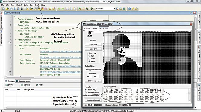
Download microC PRO for AVR. Install the software and run it. Open GLCD bitmap editor from the tool menu as shown in Fig. 3.
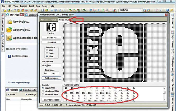
Get the byte code of the BMP image by directly loading the image in the Nokia 3310 tab as shown in Fig. 4.
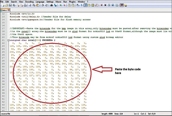
Copy the 504 bytes of byte code of the image and paste it in the source code as shown in Fig. 5.
Compile the code and burn it in the microcontroller using a suitable programmer. Connect the oscilloscope probe to the circuit as shown in Fig. 2 and the stored image will be displayed. The code is optimised and properly synchronised with time for proper display of images on the oscilloscope. Any changes in the code (addition of time delays, lines), clock frequency, crystal value, changes in settings of oscilloscope may lead to a distorted image. The code is written so that no external trigger signal is required. The image is displayed with proper synchronisation with the internal trigger signal.
The author is currently working as GET at Maruti Suzuki India Ltd, Gurgaon