


The program (adc_ch.asm) may be tested as follows:
1. Wire ATmega8535 to the LCD and the serial port through a MAX232 IC as shown in Fig. 21.
2. Connect an analogue signal (e.g., a DC voltage in the 0-5V range tapped from a potmeter or the output of LM35 used in the preceding application) to ADC Ch. 0 (pin 40).
3. Program the adc_ch.asm file into the flash memory of ATmega8535 after compilation.
4. Place the IC on the breadboard and press reset.
5. Connect the RS-232 connector of the PC through a 3-wire cable to the MAX232 pins on the board. The TXD output from ATmega8535 should go to RXD pin of the PC’s com port and the PC’s TXD output should go to RXD pin of ATmega8535.
6. Run the XTALK program on the PC and set the baud rate as ‘4800,’ data as ‘8 bits,’ parity as ‘none,’ stop as ‘1,’ and com as ‘1’ or ‘2,’ type ‘go low,’ then press ‘Enter’ key.
7. Observe the ADC data continuously on the screen.
The PC terminal program can be used to select one of the eight desired channels. For this, type any number from ‘0’ to ‘7.’ For example, to select channel-3 ADC, type ‘3.’ Remember you need not press Enter key thereafter.

The data from the PC terminal is received by the USART_RX subroutine in the interrupt mode. The main program configures the received data to interrupt the processor. In the interrupt routine, the number sent is used to change (by altering the value of the bits in the ADMUX register of the chip) the ADC channel currently chosen. Thus all the following data will pertain to this channel only and the same will be informed to the PC terminal also by sending CH3 followed by data stream.
The XTALK terminal program is given only for testing purposes. The Visual Basic program (ADC_CHSEL) provided in the EFY-CD of this month does the same. It has two windows, one of which is a Combo box for selecting the channel and the other shows the 5-digit data continuously. Selection of the channel is possible via the Combo box (Fig. 22).
Application notes with programs
You may visit Atmel’s Website ‘www.atmel.com/dyn/products/app_notes.asp?family_id=607’ for the following application notes.
1. AVR100: Accessing the EEPROM. This application note contains assembly routines for accessing the EEPROM for all AVR devices. It includes the code for reading and writing EEPROM addresses sequentially and at random addresses.
2. AVR223: Digital Filters with AVR. This document focuses on the use of the AVR hardware multiplier and general-purpose registers for accumulator functionality, scaling of coefficients when implementing algorithms on fixed-point architectures, actual implementation examples and possible ways to optimise/modify the implementations suggested.
3. AVR240: 4×4 Keypad-Wake Up on Keypress. This application note describes a simple interface to a 4×4 keypad designed for low-power battery operation.
Also there are application notes for interfacing the AVR to an IR detector much like the TV remote. Other topics of interest relating to the AVR are use of watchdog, power idle modes, SPI interfacing for communication, etc. Many have tried out the SPI interface for data communication, but it is found to be more complex compared to the RS-232 protocol. The RS-232 link for ADC data, which is described above, makes a really useful serial data-acquisition system.
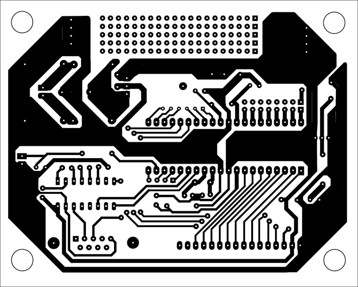
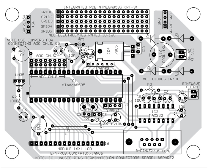
An integrated actual-size PCB layout (including the 5V power supply circuit given in Part 1) for all the applications described in this 3-part article is shown in Fig. 23. The component layout for the same is shown in Fig. 24. Suitable pads (not shown in the component layout) have been provided for wiring the components.
