


 The lost plane finder introduced here is a little on board beacon, also known as lost model alarm/crashed aircraft beacon, which helps you find a crashed or downed radio-controlled plane. The concept is to get an alert from a piezo sounder if there are no signals from the associated radio-controlled transmitter.
Usually, the radio transmitter provides a set of pulses every 20 milliseconds, which, in turn, sends the radio receiver a separate pulse to each of the servos at the same interval. In this circuit, an alarm will sound when the radio receiver no longer receives the set of pulses from the radio transmitter.

To locate the aircraft, all you have to do is switch your transmitter off and the system will start to beep. The circuit is very easy to build and does not require any special parts like costly microcontrollers. A typical lost plane finder is shown in Fig. 1.

Circuit and working
Circuit diagram of the lost plane finder is shown in Fig. 2. It is built around timer NE555 (IC1), one transistor BC547 (T1) and a few other components. The design is centred around timer chip NE555 (IC1), configured here as a missing-pulse sensor. The whole circuit can be powered with power supplies ranging from 4V up to 9V, so you can use any power source that your radio receiver/servo setup can handle.
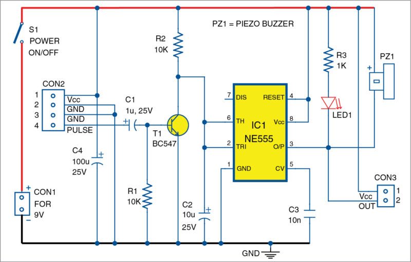
The 4-pin connector (CON2) is the input connector for the lost plane finder system, while the 2-pin connector (CON3) is an optional output connector. In the circuit, when the pulse input is available at input pin 4 of CON2, BC547 transistor (T1) is turned on and a high-level (H) voltage (near 2.6V when Vcc=4V) is available through output pin 3 of NE555 (IC1). When the pulse input is absent (transmitter is off), T1 switches off and IC1 gives a low-level (L) output through its output pin 3.

As a result, the piezo buzzer (PZ1) and the indicator (LED1) wake up to raise a noticeable alert. Presence of the optional output connector (CON3) enables driving of external low-voltage blinker/beeper loads, in case of an extreme demand for such enhancements.
Construction and testing
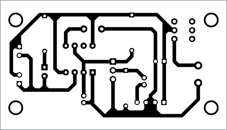
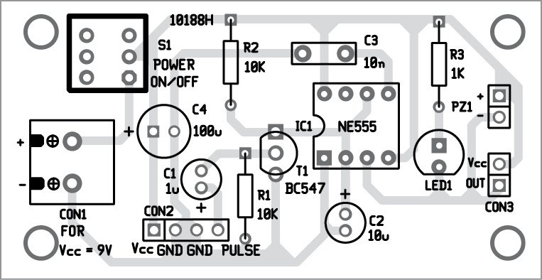
An actual-size, single-side PCB for the lost plane finder circuit is shown in Fig. 3 and its component layout in Fig.4. After assembling the circuit on a PCB, enclose it in a plastic case. A tiny perfboard is enough for the construction of the lost plane finder system. After construction, it is better to make the system vibration proof with the help of a heat-shrink tube, preferably a transparent type with appropriate diameter. Connect the finished system to any unused channel of your radio receiver through the input connector (CON2) as shown in the wiring diagram in Fig. 5.
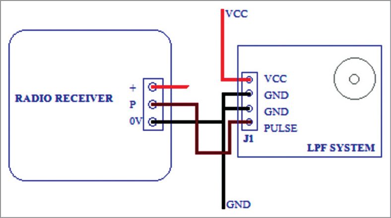
If a free radio receiver channel is not available, the system can still be utilised by sharing an occupied channel with some other intermittently-used control like landing gear, flaps or airbrakes, with the help of a Y- Splitter servo cable attached to such a channel.
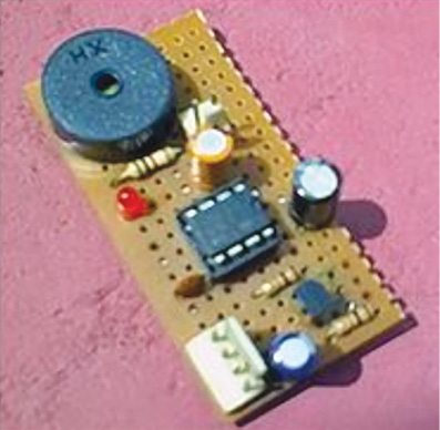
The preferred setup in the model aircraft suggests drilling a small hole in the model wall and attaching the system so that its sounder window is aligned with the hole. Depending on your aircraft model’s structure, the whole system can be completely exposed outside of the model, too. Author’s prototype is shown in Fig. 6.
Additional notes
1. Prototype was tested with R/C lithiun-polymer 2S battery (7.4V).
2. Offline test is possible by feeding servo pulses to J1 from a standard servo tester.
3. An intermittent-tone piezo buzzer (sound level 85dB to 92dB) is better than a continuous-tone type.
4. In case of an alarm malfunction, change the value of RC components (R2-C2) so that effective delay is about 30 per cent to 40 per cent bigger than the period of inputted servo pulses.
5. For a micro-size version, try to use SMD components on a stamp-size PCB.
Download PCB and component layouts: click here
T.K. Hareendran is founder and promoter of TechNode Protolabz

How does a Lost Plane Finder work?
And if can, could you also explain me how the circuit works?
Please give some video how this LPF works.
I have a problem with this locator. the locator will sound when the receiver is turned on and will go silent when the Transmitter is turn on. However, if the transmitter is turned off the locator will not turn on. I am using a Futaba 2.4 receiver. It seems the locator will not turn on when the signal is turned off. Any suggestions?
@George: As the locator will sound when the receiver is turned on and will go silent when the Transmitter is turn on, your prototype is working as configured. If the locator will not turn on when the signal is turned off, it’s because of some inherent noise problems I think. Try to change the values of C1 and R1 by trial end error method. Also see this one as a reference:
http://www.electroschematics.com/10993/lost-model-alarm-rc-planes/
Would be good if there is a video