


 Presented here is a personal weather logger whose various transducers are used to log weather data such as humidity, atmospheric pressure and temperature. The data is transferred to PC where it is displayed as a graph for analysis.
The weather logger has the following features:
1. Measures and displays real-time value of humidity, pressure and temperature on the LCD
2. Saves data for 35 hours with sampling interval of 30 minutes in the microcontroller
3. Shows clock/calendar function
4. Has USB connectivity for data transfer to PC
5. stores data in a PC for future analysis
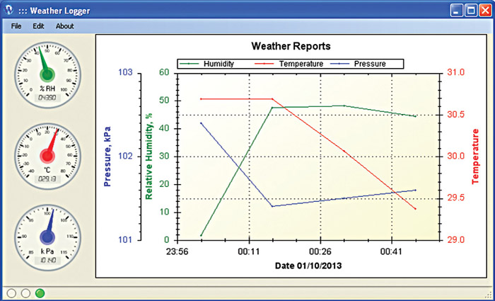
6. Displays a graph in the PC as shown in Fig. 1
7. Sets clock and reference pressure using switches
Circuit and working
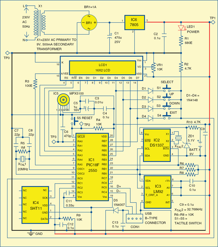
The circuit diagram of a weather logger is shown in Fig. 2. The circuit is built around microcontroller PIC18F2550 (IC1), serial real-time clock DS1337 (IC2), temperature sensor LM92 (IC3), humidity sensor SHT11 (IC4), pressure sensor MPX5100 (IC5), 5V voltage regulator 7805 (IC6) and 16×2 LCD (LCD1).

The circuit requires 5V power supply. The mains power supply is stepped down to 9V AC, 500mA by transformer X1. This stepped-down AC voltage is rectified by bridge rectifier BR1 and filtered by capacitor C1 before it is fed to IC6. Regulator IC6 provides regulated 5V DC supply. LED1 indicates the presence of power in the circuit.
Microcontroller
The PIC18F2550 microcontroller is the heart of this project. It works with a 20MHz crystal and has 32 kB of flash memory, 2 kB of RAM and 256 bytes of EEPROM. The controller is USB 2.0 compatible with speed of 1.5 Mbps to 12 Mbps. It has three external interrupts, four timer modules (Timer0-Timer3) and 10-bit ADC module with up to 13-channel multiplexer.
Real-time clock
The DS1337 serial real-time clock is a low-power clock/calendar chip with two programmable time-of-day alarms and a programmable square-wave output. Address and data are transferred serially through an I2C bus. The clock/calendar provides seconds, minutes, hours, day, date, month and year information. The date at the end of the month is automatically adjusted for months with fewer than 31 days, including corrections for leap year. The clock operates in either the 24-hour or 12-hour format with AM/PM indication.
Pins 3, 5 and 6 of serial real-time clock IC2 are connected to pins RB2, RB0 and RB1 of IC1, respectively, with pull-up resistors. At pins 1 and 2 of IC2, external crystal oscillator of frequency 32.768 kHz is connected. External 9V battery is used to power the RTC.
Temperature sensor
LM92 is a digital temperature sensor and thermal window comparator with an I2C serial bus interface and an accuracy of ±0.33°C. The window-comparator architecture of the LM92 eases the design of temperature control systems. Its open-drain interrupt (INT) output becomes active whenever temperature goes outside a programmable window, whilst a separate critical temperature alarm (T_CRIT_A) output becomes active when the temperature exceeds a programmable critical limit. The INT output can operate in either a comparator or event mode, whilst the T_CRIT_A output operates in the comparator mode only.
The host can program both the upper and lower limits of the window as well as the critical temperature limit. Two pins (A0, A1) are available for address selection.
Pins 1 and 2 of temperature sensor IC3 are connected with pins 21 and 22 of IC1, respectively. The address pins 6 and 7 are connected with Vcc as shown in Fig. 2.
Humidity sensor
The SHT11 is a single-chip relative humidity and temperature sensor module comprising a calibrated digital output. The device includes a capacitive polymer-sensing element for relative humidity and a band-gap temperature sensor. Both are seamlessly coupled to a 14-bit analogue-to-digital (A/D) converter and a serial interface circuit on the same chip. The 2-wire serial interface and internal voltage regulation allow easy and fast system integration. Pins 3 and 2 of humidity sensor IC4 are connected with pins 12 and 13 of IC1. Pin 2 is pulled up ‘high’ with resistor R9.
Pressure sensor
The MPX5100 series piezoresistive transducer is a monolithic silicon pressure sensor designed for a wide range of applications, particularly those employing a microcontroller or microprocessor with A/D inputs. This single-element transducer combines advanced micromachining techniques, thin-film metallisation and bipolar processing to provide an accurate, high-level analogue output signal that is proportional to the applied pressure.
Pin 1 of pressure sensor IC5 is connected with pin 2 of IC1. IC5 produces analogue output corresponding to the pressure at this pin.
Pins 3 through 5 of IC1 are connected with EN, R/W and RS of LCD1 to control the LCD. Pins 25 through 28 of IC1 are connected with D4 through D7 data pins of LCD1. LCD1 shows the time, temperature, pressure and humidity on the screen. Pins 15 and 16 of IC1 are connected with USB connector at D- and D+ as shown in Fig. 2. Switches S1 through S4 are used to set the pressure reference and time. Switch S5 is used to reset the microcontroller.
Working of the weather logger is simple. Once powered on, the LCD shows the real-time values of the temperature, pressure and humidity on the screen. The microcontroller stores the values of temperature, pressure and humidity every 30 minutes up to 35 hours. When this system is connected to PC via USB, all stored values of temperature, pressure and humidity are transferred to the GUI program. This program displays these values in the form of a graph on the PC screen. The ‘time’ is shown on the x-axis, and humidity, pressure and temperature are shown in y-axis as shown in Fig. 1.
Software
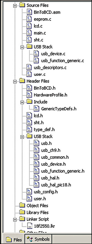
The software program for the microcontroller is written in ‘C’ language and compiled in MPLAB with C18 compiler. Add source file as shown in Fig. 3. The program is burnt in the MCU using a suitable PIC programmer.
Steps to run the Visual Studio program in PC (supports only 32-bit windows operating system) are:
1. Download the USB drivers from microchip website for PIC18F2550 microcontroller and install them in PC.
2. Connect the circuit to PC and confirm the connectivity in device manager.
3. Run executable file of Visual Studio application named ‘Weather Logger.’
4. On the left-hand side, real-time values of temperature, pressure and humidity can be seen.
Construction and testing
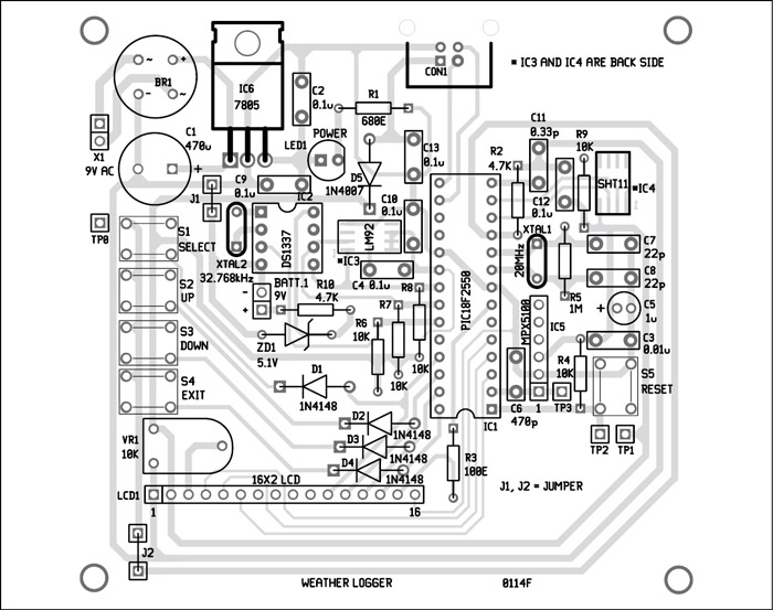
An actual-size, single-side PCB for the weather logger circuit is shown in Fig. 4 and its component layout in Fig. 5. Assemble the circuit on the recommended PCB to minimise assembly time and errors. Use IC bases for all the ICs. IC3 and IC4 are SMD ICs, so solder these ICs very carefully at the solder side of the PCB.
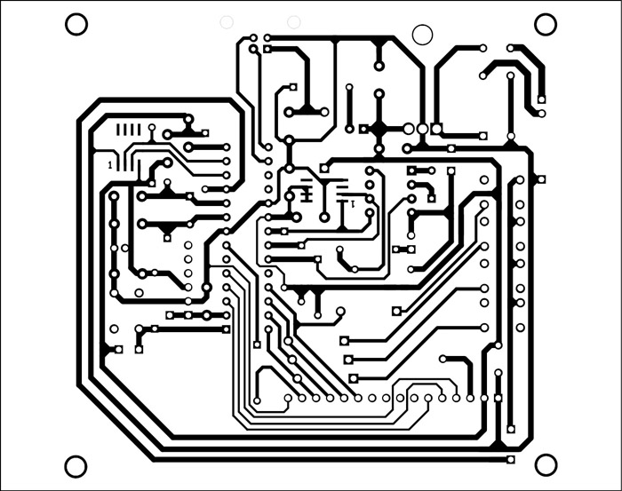
Download the PCB and Component Layout PDF: Click Here
Download Source Code: Click Here
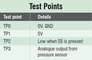
To test the circuit for proper functioning, verify 5V power supply at TP1 with respect to TP0. The reset to the system can be checked at TP2.
The author is an M.Tech in VLSI and Embedded Systems from Cochin University of Science and Technologies. He is an electronics hobbyist and amateur radio operator
This article was first published on 13th January 2015.