


We’ve developed a programmable Wi-Fi Analyzer Smart Watch that not only tracks health data but also allows users to customize and program various functionalities to suit their specific needs.
Building on this versatile framework, we’re introducing a new feature: Wi-Fi network analysis.
This functionality is invaluable for engineers configuring Wi-Fi routers and for users looking to identify the best Wi-Fi connection based on signal strength.
By adding Wi-Fi signal and network data analysis, this smartwatch goes beyond standard features, addressing a unique need in existing smartwatch capabilities and offering enhanced utility for both professionals and everyday users.
Leveraging the IndusBoard’s ESP32 Wi-Fi chip, we can seamlessly integrate Wi-Fi network scanning and analysis into the smartwatch itself.
If you’ve already assembled the smartwatch design we published in January, there’s no need for additional components—you’re ready to proceed directly to programming.
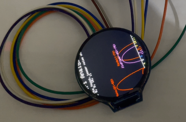
In this feature, we’ll utilize the ESP32’s Wi-Fi capabilities to scan and analyze nearby networks.
The results, including signal strength and network details, will be displayed directly on the smartwatch, adding a powerful utility for both engineers and everyday users.
Let’s dive into the design and implementation of this exciting functionality!
Components Required
- GC90A Display
- Indusboard
- Arduino GFX Library
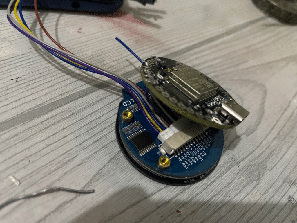
Hardware Setup
To integrate the GC90A display with the IndusBoard, follow these steps:
Power Connection
Connect the VCC pin of the GC90A display to the 5V pin on the IndusBoard to provide power.
SPI Pin Configuration
Configure the SPI interface between the GC90A display and the IndusBoard. The IndusBoard allows flexible SPI pin mapping; for this project, we’ll use the following GPIO pins:
- GPIO 21 for SCK (Serial Clock)
- GPIO 1 for MOSI (Master Out, Slave In)
- GPIO 2 for MISO (Master In, Slave Out)
- GPIO 3 for CS (Chip Select)
- GPIO 4 for DC (Data/Command)
- GPIO 5 for RST (Reset)
Pin Connections
Connect the corresponding pins of the GC90A display as follows:
- SCK to GPIO 21
- MOSI to GPIO 1
- MISO to GPIO 2
- CS to GPIO 3
- DC to GPIO 4
- RST to GPIO 5
Ensure all connections are secure before powering the IndusBoard and programming it for the SPI-based display functionality.
Coding for Wi-Fi Analyzer Smart Watch
- Install the Arduino GFX library in the Arduino IDE.
- In the Arduino sketch, configure the SPI pins for the GC90A display using the specified pin numbers (21, 1, 2, 3, 4, 5 for MOSI, MISO, SCK, CS).
- Initialize the GC90A display object using the configured SPI pins in the setup function.
Download Source Code
Connection
- Ensure the VCC of the GC90A display is connected to the 5V pin of the Indusboard.
- For SPI testing, connect the device with a 5V battery or the USB port of the Indusboard.
| Display | Indusboard |
| TFT MOSI | 21 |
| TFT_SCLK | 1 |
| TFT_CS | 2 |
| TFT_DC | 3 |
| TFT_RST | 4 |
| TFT_BL | 5V |
| VCC | 5V |
| BL | 3V |
| GND | GND |
With these components and setup, you’ll be ready to develop a Wi-Fi network analysis feature on your smartwatch using the GC90A display and Indusboard, allowing you to scan and analyze Wi-Fi networks directly from your wrist.

Download Source Code for Wi-Fi Network Analyzer Smartwatch