Reducing cable power loss is becoming increasingly important as the number of high-rise apartments and the number of floors in these buildings continue to increase. Nowadays, 20-floor apartments are very common, with buildings taller than 20 floors also becoming increasingly common. In all these apartments, the Energy Meters are located on the ground floor. Cables run from these meters to the respective apartments on each floor, with cable lengths increasing for apartments on higher floors.
With an increase in the cable length, the cable resistance increases. Due to higher cable resistance, cable losses increase. As we go to upper floors, this power loss becomes significant and can no longer be ignored. This is especially significant for high-wattage loads such as water heaters. More importantly, since these cables are installed after the meter, the consumer bears the cost of the power lost through them. If the power dissipation in these cables increases, there is a danger of fire hazard. Therefore, we have to find out how this cable power loss can be minimized.
Proposed Solution
The majority of storage-type water heaters have 2000 W heating coils. Instead of a single 2000 W heater, it is proposed to have two heater coils of 1000 W each inside the water tank. The circuit diagram of the proposed dual heater system is shown in Fig. 1.
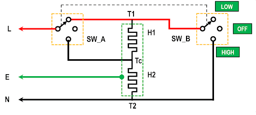
Two heaters H1 and H2 of 1000 W each are installed inside the water tank. These heaters are connected to each other at one common terminal Tc. Three cables are brought out from T1, T2 and Tc terminals of the heaters. The heater is connected to the Earth terminal of a 15 Amp three pin plug. A 2-pole 3-way rotary switch (15 Amps or higher) is used for connecting these heaters either in series or in parallel. The rotary switch position shown in the figure connects the heaters in series. When the heaters are in series, the power rating of the system becomes 500 W, according to the calculations given below:
- Resistance of each heater (H1 and H2): (230 X 230) / 1000 = 52.9 Ω
- System Resistance (H1 and H2 in series): 52.9 + 52.9 = 105.8 Ω
- Power rating (H1 and H2 in series): (230 X 230) / 105.8 Ω = 500 W
When we rotate the switch to the third position, H1 and H2 are connected in parallel, which provides a 2000 W power rating. Thus, the user has a choice of either 500 W or 2000 W power selection. With a 500 W setting, water heating time increases by 4 times. Hence, for quick heating, the user can select a 2000 W setting.
Detailed calculations for the proposed dual heater system are given below:
Assumptions:
- Cable length (Energy Meter to water heater): 100 meters
- Copper cable cross section: 2.5 sq mm
- Resistance of 100 meter cable: 0.75 Ω
- Total cable resistance (Ph and Neutral wires): 1.5 Ω
Power and Energy Calculations:
- Power rating selected: 2000 W
- Current drawn: 2000W / 230V = 8.7 A
- Power Loss in the cable: (8.7 X 8.7) X 1.5 Ω = 113.5 W
- Heater ON Time (Assumed): 0.25 hours
- Energy lost in cables: 113.5W X 0.25h = 28.4 Wh
- Power rating with dual heaters in series: 500 W
- Current drawn by dual series heaters: 500W / 230V = 2.17 A
- Power loss in cables: (2.17 X 2.17) X 1.5 Ω = 7.06 W
- Heater ON time (for same water heating): 1 hour
- Energy lost in cables: 7.06W X 1h = 7.06 Wh
- Energy saved in cables with series heaters: (28.4 – 7.06) = 21.34 Wh (75%)
From the above calculations, it is clear that, with a 500 W heater setting, energy loss in the cables is reduced by 75%. This will reduce overheating of cables and therefore reduce the possibility of fire hazards.
Limitations of Low Power Setting
As mentioned above, water heating duration increases by 4 times when the two heaters are connected in series. This may create problems for the users, especially those who have to take bath in the early mornings. Turning ON the heater one hour earlier may not be preferred by the user. To overcome this problem, we can use a Timer Switch. Timer Switches are easily available in the market. It has built-in-contactor which is used to turn ON and turn OFF electrical loads. The turn ON time and Turn OFF time is programmable. In a day, users can program several ON and OFF cycles. Timer Switches have battery backup; therefore, user settings are retained even if the power fails.
Figure 2 shows the interconnection diagram of the dual heater system including the Timer Switch. Timer Switch is connected to Mains supply using a 3 pin plug (15 Amp). Phase and Neutral wires are connected to the rotary switch. Output from the rotary switch is connected to T1, T2 and Tc terminals of the dual heater installed inside the water heater. The earthing cable goes directly to the power socket through the Timer Switch.
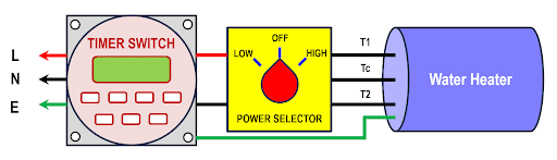
Usage: If the user wants to start the water heater in LOW power setting at 5 AM. Then, the Timer Switch is programmed to turn ON at 5 AM. The power selector switch is positioned at LOW position before the user goes to sleep. The next morning at 5 AM the water heater will turn ON and the user will get hot water as required.
Positive effect on the Grid
Every day, in the early morning, all the heaters are turned ON almost simultaneously. Therefore, the grid sees a sudden increase in the load. To meet this sudden power demand, electricity providers have to quickly ramp up generation. Many times, Peaker Power Generating units are turned ON. These are gas based generating units which can be quickly turned ON. However, the cost of electricity is much higher from these Peaker Power generators. Sudden loading of the grid may result in power supply tripping, transformers bursting (especially in the summer season).
If a large number of proposed dual heater systems are installed, then the power demand will increase gradually. Firstly, the power demand is lower because of the LOW power setting for these heaters. Secondly, with the Timer, the heaters turn ON one hour earlier. So, the electricity providers get enough time to react to the increase in power demand. It may be possible that conventional power generating units can be used to ramp up the power generation and avoid usage of Peaker Power Generators. This will save some money for the electricity providers. Incidences of power supply tripping or transformers getting burnt will reduce. Grid power losses will also reduce to some extent.
Implementation
The proposed system needs modifications to the heating coils. Therefore, only original water heater manufacturers can implement this design. The cost of a water heater using the new design will increase by about 1500 rupees. Users who are staying on higher floors may be ready to pay this additional cost. The dual heater system will provide a small reduction in electricity bill. These small savings are available throughout the life of the water heater. In a LOW power setting, the heating time is more. Longer heating time will increase the heat losses. Therefore, it is recommended to use a 5 Star rated storage water heater for implementing this design. 5 Star heaters have lowest heat loss due to superior thermal insulation.
Secondly, the electricity providers also benefit from this design, as it reduces sudden large power demand in a short time interval. Reduced load, which is spread over an hour will avoid power supply tripping and transformers getting damaged. The line losses will reduce to some extent. Therefore, the electricity boards should offer incentives to the user for installing the dual heater system. So that more and more users will opt for this design.
Prototype for Proof of Concept
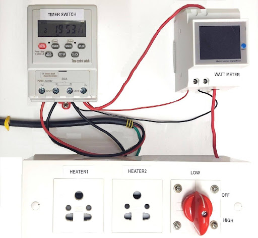
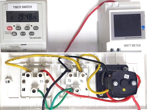
Figure 3 shows the Timer Switch, Watt Meter and Heater Sockets and Rotary Switch box mounted on a panel. Figure 4 shows the internal wiring of the Switch box. Figure 5 shows the interconnection diagram of the Timer Switch, Watt Meter and Heater Sockets and Rotary Switch box.
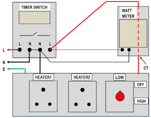
Mains power is connected to the input terminals of the Timer Switch. From the output terminals, phase wire is passed through the inbuilt CT of the Watt Meter. Also, output terminals of Timer are connected to the input terminals of Watt Meter. Now, the phase, neutral and earth wires are connected to the Heater Socket and Rotary switch box.
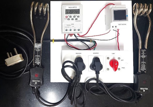
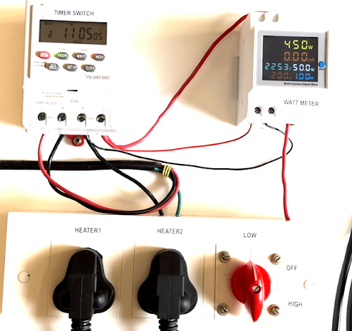
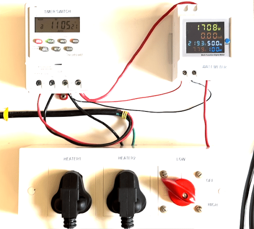
Figure 6 shows the complete assembly of the test setup including two 1000 W heaters. Before powering ON, the heaters are immersed in a bucket filled with water. The rotary switch is set at LOW position. Initially, the timer is OFF. After turning the power ON, after a few seconds the timer turns ON. The setup gets powered. We can see that Watt Meter is showing 450 W power consumption (see Fig. 7). Now rotate the rotary switch to OFF position. After that, rotate it to the HIGH position. Now the power consumption is 1708 W (see Fig. 8).
Cable power loss calculations
- Heater Power with LOW setting: 450 Watts
- Heater Power with HIGH setting: 1708 Watts
- Heater Power with HIGH setting (If No cable loss): 450 x 4 = 1800 Watts
- Cable Power Loss: 1800-1708 = 92 Watts
Thus, from the above experiment, it is clear that with LOW power setting, 92 Watts of power is saved. The actual energy savings will depend upon how much time the heater is kept ON. Note: Our apartment is on the 8th Floor. On the 8th floor itself, we are seeing 92 Watts of power loss in the cables. At upper floors, it will be much higher. Therefore, the proposed design will reduce a significant amount of energy on a daily basis. Will also reduce peak load on the grid in the early mornings.
Conclusions
The proposed dual heating coil system for water heaters reduces power loss in the cables. The longer the cable, the higher the power loss. Hence, this design is highly recommended for water heaters used in the higher floors of apartments. It uses a rotary switch to put the two heaters either in series or in parallel. With a series connection, the power rating is reduced. With a reduced power rating, the cable loss is reduced by 75%. A timer switch is proposed to turn ON the heater about one hour earlier in the mornings. This will ensure that the user gets hot water in the early morning, without getting up earlier to turn ON the heater.
This new design reduces overheating of cables and provides a small reduction in the electricity bill. Electricity providers also benefit from this design. The early morning power demand is reduced, and there is also a gradual increase in the power demand. This will help in avoiding tripping of the power supply. It will avoid the use of Peaker power generators, thus reducing the cost of electricity. Because of these benefits, electricity providers should give incentives to the user. This will offset the increased cost of the proposed design. Thus, both users and electricity providers will benefit if this design is implemented on a large scale.