


 Keep in touch with your family members from one room to another and also from outside areas such as the garage, using this intercom circuit for bidirectional communication. The advantage of this circuit is that there is no talk/listen switch as many intercoms have. The circuit is built around two low-power LM386 audio amplifiers.
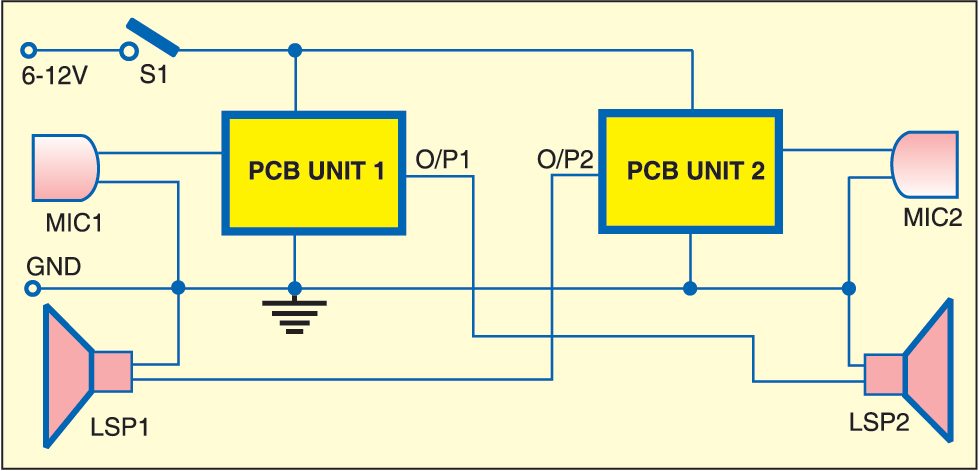
Fig. 1 shows the block diagram of the intercom system. Fig. 2 shows the circuit. It has two simple and identical channels—unit 1 and unit 2. As shown in Fig. 2, the gain of both the amplifiers (built around IC1 and IC2) is about 200, which is usually enough to work with the condenser microphones. The circuit also works with carbon microphones or other high-level and low-impedance microphones.
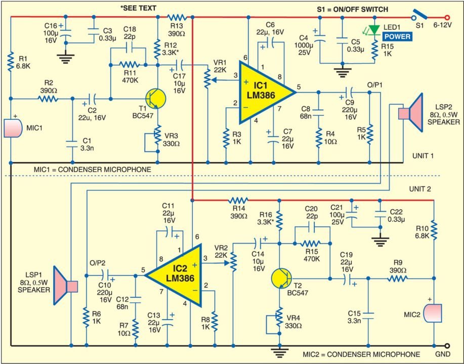
As both units are identical, working of only the first unit is described here. When you speak in front of the microphone (MIC1), the low-level signal is amplified by the amplifier built around transistor T1. Transistor T1 (BC547) is low-noise and high-gain type.

The value of resistor R11 is selected such that the voltage between the collector and emitter of T1 is approximately half the power supply voltage. Resistor R12 should have a minimal value. For example, if the emitter of T1 is connected to the ground, the value of R12 could be as low as 1 kilo-ohm (usually, the range is 680 ohms to 4.3 kilo-ohms). Use of capacitor C18 is optional. The preamplifier may exhibit instability at very high frequencies. So minimal appropriate value is chosen for resistor R1 in order to make the input circuit less vulnerable to electromagnetic noises.
Signal from the microphone is filtered by the combination of resistor R2 and capacitor C1. Capacitor C2 blocks the DC component but allows AC signal to pass. The volume is adjusted by potentiometer VR1. The potentiometer can be replaced with a preset of the same value because the volume need not be adjusted frequently. The signal is amplified by IC1 and fed to the loudspeaker (LSP2).
The second unit works in the same way as the first unit.
Assemble the circuits for units 1 and 2 on separate general-purpose PCBs and enclose in suitable cabinets. As shown in the block diagram, place microphone MIC1 and loudspeaker LSP1 in the first room, and microphone MIC2, loudspeaker LSP2 and the entire electronics block plus the power supply in the second room. Keep the interconnection cables as short as possible—preferably shorter than 10 metres. These should be kept away from the cables of the mains power supply and other sources of electromagnetic interference. Use a shielded cable for connecting the microphone to the circuit.
It is important that there is no acoustical feedback between the microphone and the loudspeaker on both the sides. So the microphones and the loudspeakers should not face each other. As the gain of each channel is not very high, the probability of acoustical feedback is low. In case of acoustical feedback, lower the volume of the amplifier and change the positions of the microphones and loudspeakers.
The preferred power supply for the circuit is 6V or above but the circuit also works with regulated 5V from IC 7805 (not shown in the diagram). If a higher dynamic range is needed, the power supply should be 9V or even 12V. For power supply, you can use an AC-DC wall adaptor, dry batteries or rechargeable batteries.
pcb layout please