


 Here is an IR receiver module tester for on-board testing of IR modules used for remote control of TV sets and VCD players. The circuit is very simple and can also function as a remote tester.
IR Receiver Module Tester
IR receiver modules are miniature IR receivers sensitive to pulsed infrared rays. These have a pin photo-diode and a preamplifier stage encased in an epoxy case that acts as the IR filter. Internally, the module has an AGC, band-pass filter, demodulator and control circuit. Its output has a bipolar transistor with 80- to 100-kilo-ohm resistor in the collector. Normally, the collector output of the transistor is high and gives 5V at 5 mA. The output of the module is active-low and hence it sinks current when the pin photo-diode senses the presence of pulsed IR rays.


The IR receiver module is designed with high immunity against ambient light and is capable of continuous data transmission at up to 2400 bps or higher. The band-pass filter and AGC suppress unexpected noise to avoid false triggering. The module responds to the IR beam only if its carrier frequency is close to the centre frequency of the band pass.
Circuit operation
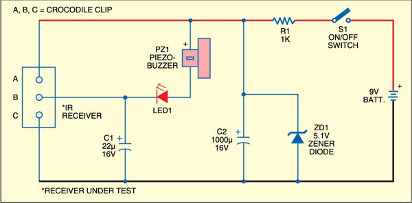
Three mini crocodile clips are used to connect the circuit to the positive, negative and output of the module. If the module is properly working, its output remains 5 volts. This makes the cathode of LED1 high. So LED1 doesn’t glow and the buzzer remains silent.
When you focus the remote handset onto the IR receiver and press any switch, the output of the IR receiver sinks current. So LED1 starts flashing and the buzzer beeps in sync with the pulsations of the IR beam. On the other hand, if your IR receiver module is faulty, the output of the module does not sink current when you focus the remote handset towards the module and press any switch. So neither LED1 flashes, nor the buzzer beeps in sync with the pulsations of the IR beam.
Power to the circuit is obtained from a 9V PP3 battery and regulated to 5 volts by zener diode ZD1. Most of the IR receiver modules work only between 3 and 6 volts. Storage capacitor C1 releases current to make LED1 flash brightly. (EFY Note. We had used a TSOP1738 IR receiver module while testing. Fig. 2 shows the pin configuration of TSOP1738.)

Construction & testing
Assemble the circuit on a small piece of matrix board and enclose in a small cabinet. Use a high brightness red LED and a small buzzer for audio-visual indication. Connect points A, B and C to the crocodile clips using red, black and blue wires to connect to the pins of the module easily. For easy identification of pins, the pin assignment (front view) of some common IR receiver modules is shown in the table.
The article was first published in January 2009 and has recently been updated.