


While LPG leakage detectors are widely available, they are often costly and rely on microcontroller-based designs. Here, we present an affordable, easy-to-build LPG leakage detector that eliminates the need for expensive components.
The primary function of this circuit is to detect LPG leaks efficiently. Figure 1 showcases the author’s working prototype.
Table of Contents
Required Components
Circuit and Working of the LPG Leakage Detector
Circuit diagram of the low-cost LPG detector is shown in Fig. 2. It is built around step-down transformer X1, two rectifier diodes 1N4007 (D1 and D2), a 1000µF capacitor (C1), 7805 voltage regulator (IC1), MQ-6 LPG gas sensor (GS1), dual comparator LM393 (IC2), darlington transistor TIP122 (T2), 12V high-gain siren/buzzer (PZ1) and a few other components.

The mains supply is reduced by transformer X1, rectified by diodes D1 and D2 in a full-wave rectifier configuration, filtered by capacitor C1, and stabilized at 5V DC by voltage regulator 7805 (IC1), supplying the necessary power to the circuit
At the heart of the circuit is dual comparator IC LM393 (IC2). It is used to compare two different voltages, namely, reference voltage and MQ-6 gas sensor output voltage.
Reference voltage at non-inverting pin 3 of IC2 is set using potentiometer VR1 to adjust voltage levels based on sensitivity requirements. LPG sensor (MQ-6) output voltage is fed to inverting pin 2 of IC2.
When the reference voltage at pin 3 of IC2 is lower than the sensor voltage at pin 2, the output goes low, indicating no LPG leakage. With low output, T1 remains cut-off and there is no current flow through the buzzer; it does not sound and remains in silence mode.
If reference voltage is greater than sensor voltage, output goes high, which means there is LPG leakage. The high output switches on transistor T1 and the buzzer rings loudly to alert the people around.
Detecting gas leaks becomes effortless with this circuit, as it leverages inexpensive components and offers adjustable sensitivity using the VR1 potentiometer to suit various environments.
LPG Leakage Detector PCB Design
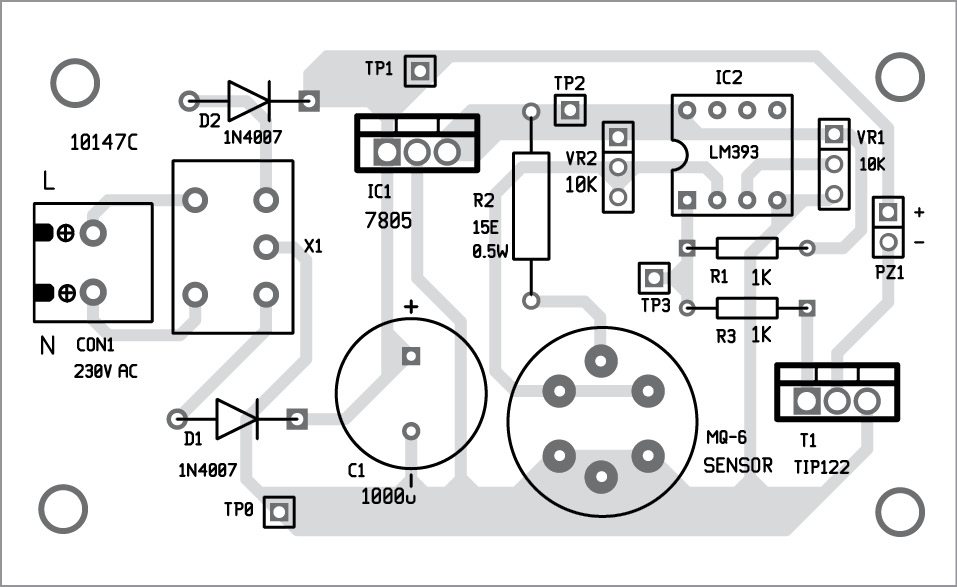
An PCB pattern of the LPG leakage detector is shown in Fig. 3 and its component layout in Fig. 4.

Download PCB and component layout PDFs: click here
Testing LPG Leakage Detector
After assembling the circuit on a PCB, enclose it in a box with an opening for the gas to enter. Place the unit near the LPG cylinder or gas stove, within a distance of one meter. Vary preset VR1 to adjust sensitivity of the sensor.
Verify the voltages are as per test points table before using the circuit. Now, spray the gas from the bottle (as shown on the left side of author’s prototype) towards MQ-6 gas sensor and measure voltage at TP3; it should be high.
If you do not have a gas-filled bottle, place the LPG leakage detector near the gas stove burner and turn it on for a few seconds without igniting. Then, turn the burner off and adjust VR1 until buzzer sounds.
Check other related Projects:
Pamarthi Kanakaraja is associate professor (R&D cell) in Usharama College of Engineering and Technology, Andhra Pradesh. He has been working in the field of embedded designing and programming concepts for the last six years.
This article was first published on 5 September 2016 and recently updated in October 2024.
Very good site for student
Good
i want to do this project so can you please tell me the name of the spray bottle you are used in this circuit as per your prototype?
Here’s the reply from the author Pamarthi Kanakaraja “Proflame portable gas cartridge, Company name: Godrej,
I bought this product from Vijayawada Besant Road, AP”
where is vijayawada besant road,AP”???????????
Can u give image of Mount component circuit
What is the overall cost for this project???n is it materials are easily available??
Instead of this we use Normal body spray????
offcourse
Can you please share the design of the project?
can u say details about the block diagram
Which block diagram? The circuit explanation is given under Circuit and working section
Instead of the transformer and diode, capacitor. Can u use just 12v already made supplie? And if yes, wouldn’t that voltage regulator get too hot because the volatage difference is high (12-5=7v)
The sensor containing a heating element which is very sensitive to voltage, only 5V+-0.2V should be apply to it. Otherwise it will get burn.
Very useful for trainers and trainees to motivate themselves
what is it’s range i mean can it detect leakage in room??
cost estimation of LPG leakage detector.
good
good but i have doubt what spray that u used???????????????
how to connect gas sensor?
6-pin Gas sensor is easily available in the market. You can directly insert the sensor into the PCB the space provided for the same. However, please note that you cannot use directly with the 4-pin gas sensor module available in the market.
it is very good project but for more understading easily its connection soldering can u upload a demonstration video
Wiring of gas sensor is not clear,plz tell w.r.t pin
sir please mail these project on my mail id.
Sir I am not able to get an output. Is this circuit correct?
The author Pamarthi Kanakaraja replies.
“I checked and verified the results again. It’s perfectly ok. The circuit and components specifications are correct. There is no factual mistake in the circuit.
If you are not getting the output, the fault can occur due to the wrong settings of variable resistors VR1 & VR2.
1)VR1 is used as reference voltage. It must set based on MQ6 sensor output value.
2)VR2 is used to set the sensor sensitivity.
Also, some sensors did not work properly due to manufacturing defects. If you suspect that you may change a new sensor and give it a try again!”
i want more information about this low cost LPG detector project because i want to write black book on this & i made this first time it gives output but next time it didn’t, so what should i do please tell me?
please reply
Sir we are doing mini project on this
But im little confused about connections which i made
Sir can u plz send ur ckt buildup image.
Hi Priya, all the information are present in the article itself.
Mujhe MQ6 ka PCB layout nhi mil rha… Mai PCB design kaunse software pe kru
i have one gas sensor mq6 fitted in a pcb
but it has only four pins (vcc,gnd,a0,d0)
how to connect it in circuit?
https://tse4.mm.bing.net/th?id=OIP.KzJm7ouJVyqnt1ZKpoan9gAAAA&pid=Api
my sensor like this
Either you can remove the sensor from the PCB you have(4pin PCB) or you can find the pin details of MQ-6 from Google.
Sir, please tell about the pins of mq 6, that which is to be shorted and which is to be connected to the circuit.
Sir we are doing mini project on it if u have a video send to me sir
Sir I have a one equation about ckt distance ….when increase the distance then its not work then tell mi some information about this.
Sir when switch on the circuit buzzer shout without applying any gas on the sensor please answer about this sir
What is role of duel comparator in this project can we replace it by single comparator
What is the role of dual comparator in this project can we replace it by single comparator
You can use a single comparator IC. LM393 IC was used by author because it is easily available in the market.
What happen if we use single comparator
Instead of dual comparator
You can use a single comparator IC. LM393 IC was used by author because it is easily available in the market.
Sir we are doing mini project on it so can u send the video , we are bit confused
Sir can u please tell me how and why that reference voltage goes high compared to sensor voltage
I didnt understand that point please clarify my dout
Sir where can I get the finished product on a continuous basis
I want to make a machine to detect lpg gas leak( cylinder body leak, bunk leak or valve leak) that can be installed in a coveyor and check every lpg filled cylinder online before it is passed to the sealing process. Hey anybody can help me in this project?
What is TP1,TP2,TP0??
Hi, I connect the components according to the diagram. But when I spray the gas it didn’t do anything. What can I do?
I was fabricate this circuit but it is not working why ?
You use 12-0-12 750mA step down transformer so how you get 16volt dc at TP1 testing point.
Plz reply
Thanks for your interest in our circuit! The problem could be related to power supply in the circuit. First check that you are getting the voltages as given in the test point table in the article. A filter capacitor is connected across the secondary of the 12V-0-12V, center tapped transformer. The voltage across the capacitor will be more than 12V because it will tend to charge to the peak of the AC waveform. So you will get somewhere around 16V at TP1.
CAN YOU PLEASE MAIL US THE REPORT OF THIS PROJECT AS SOON AS POSSIBLE.ITS URGENT,OR SOME REPORT RELATED TO THIS PROJECT.PLEASE SIR/MAAM ITS URGENT. pleaseeeeee……..
HI Rupali, all the information are present in the article itself.
How do you determine the value of the resistors? Pls explain
There are many resistors-which value(s). Variable resistors are used by hit and trial method, others are specific to associated components
IF we use the gas sensor readymade module how we connect the module in this circuit ?
please reply with connection diagram.
How can we contact you about the project in Vijayawada?
You can contact me at [email protected]
final output not getting
what is the problem
buzzer Continuously Ring
Check again by varying VR1 and VR2. Also check proper connection of transistor T1, if problem still exists replace T1 with fresh one.
please mail everything you have on this project
[email protected]
Can you please share the simulation of this project on any software it is required for educational work.
Sorry we do not have simulation code for this project.
Hey
How would I get full copy of Low cost LPG LEAKAGE DETECTOR?
Hi Ahmad, this is the full article.
Can you please share the PCB and Component layout of this project?
Hi Saurabh, we have shared the files via email. Also, you can download it from the article itself.
hello i have a question about the VR2 pot.meter what does it do? i cant seem to find it in the description. Im making this project for my graduation and i need some info please. thank you