


 Need a quick power boost? This simple circuit converts 12V DC to 230V AC. Perfect for relaxing with a night lamp or charging your phone. Want to power more stuff? Simply add some extra MOSFETs and watch it go!
Battery Charger Circuit
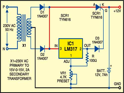
This circuit has a two stage-battery charger with cut-off and battery level indicator and an inverter circuit. Charging circuit is built around IC1 (LM317) as shown below. When mains 230V AC is available, IC1 provides the gate voltage to SCR1 (TYN616) through diode D3 (1N4007). SCR1 starts charging the battery. For output voltage setting preset VR1 may be used.
The battery level indicator & inverter circuit is shown below. The battery level checking system is built around transistors T1 and T2 (both BC547) along with some discrete components.

When the battery is charged (say, to more than 10.50V), LED1 glows and piezo-buzzer PZ1 does not sound. On the other hand, when battery voltage goes down (say, below 10.50V), LED1 stops glowing and piezo-buzzer sounds, indicating that the battery has been discharged and needs recharging for further use.
Inverter Circuit
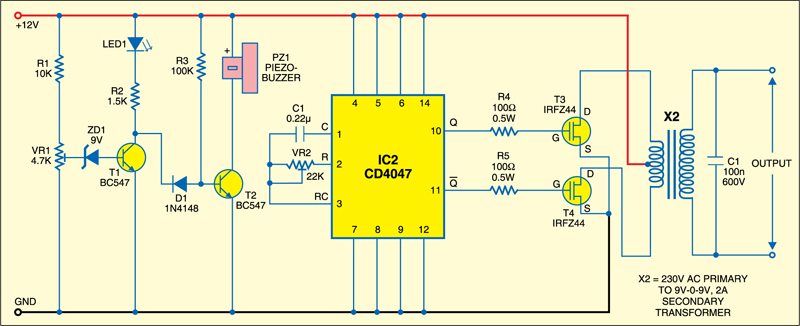
The inverter is built around IC2 (CD4047), which is wired as an astable multivibrator operating at a frequency of around 50 Hz. The Q and Q outputs of IC2 directly drive power MOSFETs (T3 and T4). The two MOSFETs (IRFZ44) are used in the push-pull configuration. The inverter output is filtered by capacitor C1.
Construction and Testing
Assemble the circuit on a general-purpose PCB and enclose it in a suitable metal box.
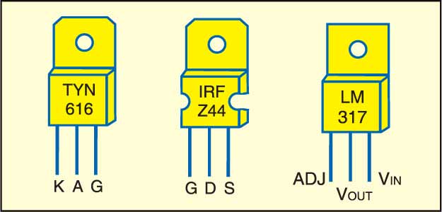
Refer the pin configurations before mounting the components on the PCB. Mount the transformer on the chassis and the battery in the box using supporting clamps. Use suitable heat-sinks for MOSFETs.
The circuit can be used for other applications as well by delivering higher power with the help of a higher current rating transformer and additional MOSFETs.
Safety and Protection Measures
- Fuse Protection: Use fuses on the input and output to prevent short circuits and overcurrent damage.
- Snubber Circuit: To prevent voltage spikes, connect a snubber across MOSFETs.
- Heat Management: To reduce overheating, attach heat sinks to MOSFETs and consider using a fan with higher power.
- Voltage Protection: Install cutoff circuits to disconnect the battery when the voltage falls below 10.5V or during voltage surges.
- Insulation: To avoid shocks, insulate high-voltage components and utilize a grounded metal casing.
Testing and Troubleshooting
- Initial Check: Inspect all connections and component orientations to ensure there are no short circuits.
- Voltage Testing: Measure the output without a load for 230V AC and confirm the CD4047’s 50Hz frequency.
- Load Testing: Begin with a modest load and gradually increase, checking for temperature increases in components.
- Common Fixes: Check the frequency of oscillations for low output; enhance ventilation or utilize a lower load for overheating; and modify output filtering for flickering.
Application and Practical Case Studies
- Backup Power: During power outages, used as backup power to power small equipment such as lights and fans.
- Portable Outdoor electricity: Use automobile battery electricity to run camping lights or small AC equipment.
- DIY Solar Projects: Pair with a solar panel to create a low-cost, off-grid AC power source.
- Education and prototyping: Ideal for studying the fundamentals of DC-AC conversion as well as practical electronics.
The article was first published on 5 February 2018 and has recently been updated on 28 October 2024.


asslm… hi bro,.. i am from indonesia,.. i need permission about your schematic diagram, i’ll use it for my project,..with some little modification,.. i use 20x irfz44 will build for my customer,.. please,.. thanks for sharing..
Huda, you can use the Schematic.
I m using 9-0-9 1A transformer instead of 2A will it work
What is a rating of 12V battery …? Which battery can i use ?
12V, 7Ah lead-acid rechargeable battery was used during testing.
Please send video how to connect the micro inverter using cd4047 with battery level indicator circuit
does the voltage between cathode of SCR and ground is same as the voltage between gate of SCR and ground?
I mean by changing preset VR1, voltage at gate also changes, so will the voltage also change in cathode also or it will remain the same
how to add more mosfet in it..plzz help
Hi sir,
I want to build 5.5kva power inverter that can carry refrigerator and blender.
Kindly assist me sir with such circuit diagram.
My name is paul Emmanuel
And here is my email: [email protected]
Charging cut off and deep discharge cut off not provided.
Dear sir
Can I get your contact no
[email protected]
How much current can be drawn by this circuit? And I would like to know why we used a step-down transformer instead of a step-up transformer.
Great project, currently working on it.
Thank you for your feedback.
Does LM 317 works properly without any dc filter capacitor ? Because only pulsating dc was used in the circuit. Waiting for reply. Thank you,sir.
It is recommended to use input filter capacitor (say 1000uF) to improve input transients in practical circuits.
An optional capacitor (say 1uF to 10uF) can be used at the output.
I need this project PCB. Can you Send me please? Thanks
This PCB is not available, sorry.
Your project is quite interesting. I am rather new to electronics. I wish to enhance
the output to about 1,00W. Is it possible for me to use the same components up to
the IC CD 4047 and use several IRFZ 44 FETs in parallel plus a Transformer of high
capacity? Please let me know the values. Look forward to your advice.
Best regards.
Kithsiri
This is a great project please send me the schematic diagram my name is Goodson Siame ,am from Zambia Africa.
Thanks for the feedback! The schematics are given in this article, however, PCBs for this project are not available.
Please help me to design pure sine wave inverter of capacity 2A. I also want to learn SMPS design. Do you provide training classes?
Thanks
CHANDER SHEIKHER
You may refer to Sinewave inverter from here https://www.electronicsforu.com/electronics-projects/sine-wave-inverter-circuit. For SMPS refer to https://www.electronicsforu.com/electronics-projects/simple-12v-smps and https://www.electronicsforu.com/electronics-projects/smps-reference-designs
Please, could you provide charging and charging complete LED indicators for the “Battery charger with cut-off circuit” ?. Thank you for your immense support.
Is there any base papers and any successful prototype of this project,as we are trying to do this project in our college for our pass percentage,plz kindly msg me on this number if any were there
No.9000321950
hom much total cost in this project?
Dear Naveen,
We would like to inform you that all the information we have regarding this topic has already been provided in the article itself. Unfortunately, we do not have any additional base papers or details about successful prototypes to share.
Best regards,