


 Most of the mobile phone complaints are related to the power supply. This is mainly because of improper charging and use of non-recommended chargers and low-quality batteries. Depending upon the make and model, the charging time of mobile phones varies from 1 hour to 3 hours. The charging current is also different for different models. So it is better to use the charger specified by the company only.
Equipment for measuring the capacity or the backup time of a battery are not readily available in the market. But by measuring the charging and discharging currents, the approximate backup time of a battery can be found out. For example, charge a battery of 4.8V, 400mA rating for 1 minute and check whether it can discharge for 1 minute through a 400mA torch bulb.
If the battery is discharged fully, it would not get charged again through a normal charger. The battery would require an initial charge or boosting.

Mobile Phone Multipower Unit Circuit
Here’s a multipurpose circuit (see Fig. 1) for battery boosting as well as normal cellphone battery charging. You can boost the battery at 400 mA for two minutes and then charge using a normal charger or this car charger. Other features of this circuit are a variable regulated DC voltage output (0-12V), voltage display panel meter, provision to measure charging/discharging current, ammeter, and micro soldering iron.
The supply voltage for the whole unit is given by a 230V/18V, 2A transformer. This is rectified by a bridge rectifier (1N5408 x 4), filtered, and given to the ICs (IC1, IC2, and IC3) of regulator 7812. Another regulator IC (7805) gives regulated 5V to the voltage display panel meter. The center tapping of the transformer is connected to LM7805. The panel meter displays the variable output voltage (0-12V). It is a 3½-digit LED display module, which is readily available in the market.

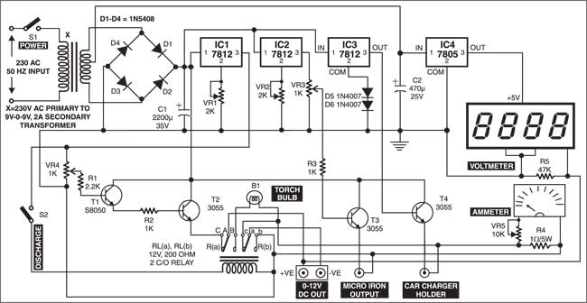
Since pin 2 of IC1 (IC 7812) is grounded through a 2-kilo-ohm preset (VR1), it produces an output voltage of 13V (12V+voltage drop across the preset). You can increase the output of IC1 up to 18V by varying the preset.
The output voltage of IC1 is given to transistor T1 (S8050) through 1kilo-ohm potentiometer VR4 and 2.2-kilo-ohm resistor R1. Potentiometer VR4 acts as the boosting voltage controller. The function of 2.2 kilo-ohm resistor is to limit the boosting current. Transistor T1 acts as the pre-current amplifier.
Power transistor T2 (3055) works as the current amplifier, while 1-kilo-ohm resistor R2 acts as a current limiter to transistor T2. The emitter of T2 is connected to point C of a 12V, 200-ohm relay.
Circuit operation
In normal condition, discharge switch S2 is opened and points ‘A’ and ‘a’ of the relay are closed to ‘C’ and ‘c’, respectively. Hence the boosting out terminals get a supply of 12V maximum. This voltage can be varied from 0 to 12V by using boosting voltage controller VR4. The mobile phone battery is boosted from this variable DC output. The boosting voltage is also given to the digital voltmeter or panel meter for display of the variable DC output.
A volume unit (VU) meter is used for measuring the charging and discharging current. It works from 0.1V to 1V (max.). Within this voltage range, it reads a load current of maximum 1 amp. The maximum current reading can be set with the help of 10-kilo-ohm preset VR5 connected to the VU meter.
The VU meter, boosting terminal, and car charger are connected to ground through 1-ohm, 5W resistor R4. So the VU meter displays the current taken while charging and discharging according to the voltage drop across this resistor.
When discharge switch S2 is switched on, relay RL energises and points ‘A’ and ‘a’ come in contact with points ‘B’ and ‘b’, respectively. Now if a battery is connected to the boosting terminals, it discharges through the discharge bulb and the V-U meter reads the discharging current.
On adjusting 2-kilo-ohm preset VR2, IC2 (IC 7812) gives an output of 16.5V. This voltage is given to transistor T3 (3055), which works as a current amplifier, through 1-kilo-ohm potentiometer VR3 and 1-kilo-ohm current-limiting resistor R3. Potentiometer VR3 works as the voltage control for micro-tip soldering iron. A standard micro-tip iron needs 16V DC maximum to heat up to 300°C. The micro iron current amplifier drives a micro iron of 1W to 25W.
Regulator IC3 (IC 7812) produces an output of 13V by making use of diodes D5 and D6 connected in series at pin 2 towards ground for dropping 1V. This output is given to power transistor T4 (3055), which works as a current amplifier. An output of 12.5V is obtained at the collector of T4, which is given to the car charger.
Circuit applications
The car charger works on DC and it has an inbuilt voltage regulator and current limiter. The input of car charger varies from 4V to 12V. The outputs of different car chargers depend on the make and model. Each charger has its own connector for connection to the mobile phone. The charger holder given here can be used to connect any model of car charger for charging a mobile phone battery.
Normally, mobile phones have a voltage rating of 2.4V to 4.8V. Be careful while connecting a substitute power supply, as even a slight increase in the applied voltage can damage the phone.
Some phones go dead due to a shorted RF power amplifier. If a battery is connected to such a handset, it may suddenly get fully discharged and become dead.
Thus it is advantageous to verify the overall loading of the handset before connecting an external power supply or battery. For the purpose, you can use an ohmmeter. The battery terminal of the handset reads 5 to 50 ohms in one direction and 1 kilo-ohm to 150 kilo-ohms in the other direction. If a wide difference is noted, the circuit is either open or shorted.
The article was first published in September 2003 and has recently been updated.

12volts DC mobile charging jo ki trasister no 8050/8550 mila kar Kese banayeng