


 Nowadays, high-power light-emitting diodes (LEDs) LXHLMW1C are available in the market. These white LEDs contain indium-gallium-nitrogen (InGaN). The LEDs’ emitting capacity is 20 candela (Cd). We can use these LEDs for automatic garden lighting and wide voltage operation by applying different voltages.
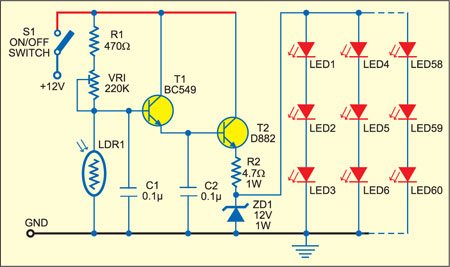
Fig. 1 shows the circuit for automatic garden lighting. Switch S1 connects 12V to the circuit built around transistors T1 and T2. Light-dependent resistor LDR1 is used to sense the light intensity and preset VR1 is used to adjust the threshold of light. The resistance of LDR remains low in daylight and high at night (in darkness).
In the morning, light falls on LDR1 and transistors T1 and T2 are cut-off. As a result, 12V supply is not available to the LEDs. In the evening, when no light falls on LDR1, transistors T1 and T2 conduct to provide 12V to the LEDs. This turns on all the LEDs (LED1 through LED60). The on/off switching level can be adjusted by 220 kilo-ohm preset according to the intensity of the light.

The emitting capacity of LEDs (UW-510CWH) used here is 8 Cd. Since a total of 60 of these LEDs have been used, this unit will provide luminous intensity equivalent of 480 Cd. The LEDs are arranged in twenty rows, with each row having three LEDs in series. The input voltage is approximately 12V and all the LEDs are spaced 1 to 1.5 cm apart.
The entire circuit, except LDR1, can be assembled on any general-purpose PCB. House the PCB in a box and, using two long wires, mount LDR1 at a place where light falls on it directly. Now place the unit in your garden.
You can use the switching section for other systems as well. You just need to remove the LED section from the circuit and connect the switching section to the desired system. So the system will now automatically switch on in the evening and switch off in the morning.
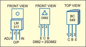
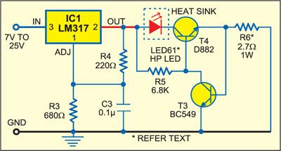
Fig. 2 shows a wide-voltage operation circuit. Here, the high-power LED61 (LXHLMW1C) gives a power equivalent of 20 Cd. This LED has a metallic back for mounting on a heat-sink. Its rated maximum input DC voltage and current are 3.6V and 350 mA, respectively. Regulator IC LM317 (IC1) provides a constant voltage of 4.7V. Resistors R3 and R4 limit the current through the LED. The LED is very sensitive to voltage inputs. In the 2.5V-3.5V region, each millivolt variation changes the current through the LED logarithmically. Transistors BC549 and D882 (T3 and T4) and resistor R6 provide a constant current to LED61. The unit gives a constant lighting for voltages ranging from 7V to 25V.
Fig. 3 shows pin configuration of regulator LM317 and transistors D882 and BC549. Use heat-sinks in regulator LM317 and transistor D882 before soldering them onto the PCB.

nice job, thanks
You are most welcome.