


 Most water level indicators for water tanks are based on the number of LEDs that glow to indicate the corresponding level of water in the container.
Here we present a digital water-level indicator. It uses a 7-segment display to show the water level in numeric form from ‘0’ to ‘9’.
Water Level Indicator Circuit Diagram
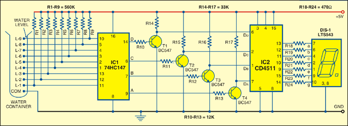
The circuit works off a 5V regulated power supply. It is built around priority encoder IC 74HC147 (IC1), BCD-to-7-segment decoder IC CD4511 (IC2), 7-segment display LTS543 (DIS1), and a few discrete components. Due to high input impedance, IC1 senses water in the container from its nine input terminals.

The inputs are connected to +5V via 560-kilo-ohm resistors. The ground terminal of the sensor must be kept at the bottom of the container (tank). IC 74HC147 has nine active-low inputs and converts the active input into active-low BCD output. The input L-9 has the highest priority.
The outputs of IC1 (A, B, C, and D) are fed to IC2 via transistors T1 through T4. This logic inverter is used to convert the active-low output of IC1 into active-high for IC2. The BCD code received by IC2 is shown on the 7-segment display LTS543. Resistors R18 through R24 limit the current through the display.
Operation & Working
When the tank is empty, all the inputs of IC1 remain high. As a result, its output also remains high, making all the inputs of IC2 low. Display LTS543 at this stage shows ‘ 0, ‘ which means the tank is empty. Similarly, when the water level reaches L-1 position, the display shows ‘1, ‘and when the water level reaches L-8 position, the display shows ‘8.’
Finally, when the tank is full, all the inputs of IC1 become low and its output goes low to make all the inputs of IC2 high. Display LTS543 now shows ‘9,’ which means the tank is full.
Assemble the circuit on a general-purpose PCB and enclose in a box. Mount 7-segment LTS543 on the front panel of the box. For sensors L-1 through L-9 and ground, use corrosion-free conductive-metal (stainless-steel) strips.
More interesting projects are available here.

Please why did you choose those particular resistor values? The 560K, 12K, 33K and 470 ohms resistors.
Resistors are mostly using for resist current flow, Here in 74HC147 is a Cmos logic ic and its input pins has current limitations of micro ampere. That’s why maximum resistance 560k has used here. 12 K resistance are base resistance which limits the current flow to the base because if it is more then CE current flow will be much bigger and will cause braking of transistor. BC547 need only .7 v and .05mA current at base to turn the transistor on . that’s why 12k is using at base. generally this transistor has a high base resistance . The resistance 33K used because the next IC CD4511 is another CMOS IC and having limitation in the input signal current . thats why CE region of BC547 has 33k . 470 ohm resistance has connected before 7 segment display. we know that 7 segment has 7 led inside and we also know the power have to give to light up so 470 has used to limit the current flow. all these resistance has chooses with respect of ohms law equation and electrical parameter of components
How much difficult is it to incorporate a level control and alarm?
For example. L1, L9 low and high level alarm. L2, L8 Start and Stop of water pump control.
Is it possible to use COMMON ANODE DISPLAY WITH CD4511? If yes what are the modifications in circuit ?
Here’s the reply from author Daniyal Syed :
To use a common anode display, please remove the inverting transistors between the IC 74147 and BCD to 7-Seg decoder. Change the 7 Seg decoder to IC 7447 or equivalent and use a common anode display. The circuit should work fine.
sir i want 18 level water level indicator circuit diagram.
How does high input 1s in IC1 is inverted into 0s?
is it done by IC1 itself?
How can I order above kit on online?
You can order the kit from this link.