
 We build this weather monitoring system using Arduino that provides information such as temperature and humidity on a color touch-screen display. It can also control the temperature through the touch-screen user interface when it exceeds the set threshold level.
The project can be easily converted to a personal weather station by adding more sensors to measure weather conditions outdoors or indoors.
The digital console provides easy readouts of the data collected by the sensor. The touch-screen has a microSD card memory slot. So, it can be connected to a personal computer where data can be displayed, stored, and uploaded to websites, or used for data ingestion or distribution systems.


Below you can see the demo video of this weather station project…

DIY Weather Station Required Components
TFT Touchscreen Display
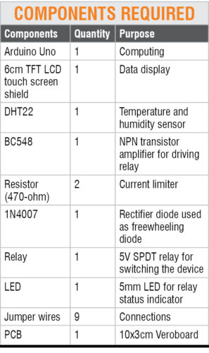
The 6cm TFT touch-screen display TS1 is basically an Arduino shield, which can be mounted on top of the Arduino Uno board. This is one of the advantages of this display because you don’t need any external wires to interface with Arduino.
We have previously discussed how to use TFT display with Arduino.
Arduino Uno
It is the heart of the project. Temperature and humidity data, TFT touch input display, and device control inputs are processed through Arduino programming.
DHT22
This temperature and humidity sensor gives more accurate readings as compared to the popular DHT11 sensor. With this sensor, you can easily program to get humidity in %, and temperature in °C and °F units. In this project, its output pin is connected to pin 11 of the Arduino board.
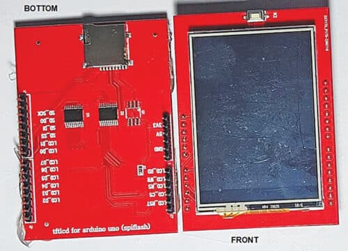
DHT22 sensor can either be purchased as a sensor or as a module. The sensor comes as a 4-pin package out of which only three pins are used. The module comes as a 3-pin package, as shown below.
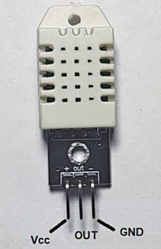
The module has a filtering capacitor and pull-up resistor inbuilt, but for the sensor, you must use them externally, if required. Otherwise, the performance of both is same. The sensor is also factory calibrated and hence easy to interface with microcontrollers. It can measure temperature from -40°C to +80°C and humidity from 0% to 100%.
BC548
This popular bipolar NPN transistor is used as a driver for switching the electrical appliance connected across the relay module.
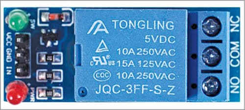
Relay Module
This electromechanical sugar-cube, a single-channel relay is used to switch on/off the electrical device connected across its COM and NO terminals. You can use a readily available single-channel relay module. In that case, you can connect digital pin 11 of Arduino to IN pin of the relay module.
Weather Monitoring System Circuit Diagram
The circuit diagram of the weather station with device control is shown below. It comprises Arduino Uno Board, DHT22 temperature and humidity sensor, BC548 transistor T1, a 5V single changeover relay, light-emitting diode LED1, and resistors R1 and R2.
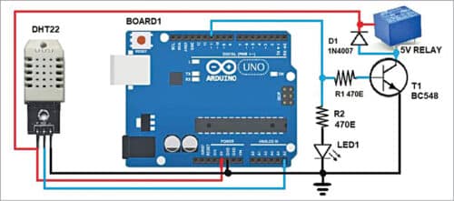
A 9V-12V DC power supply is used to power the Arduino board. The 5V supply from the Arduino board powers the touch-screen, DHT22 sensor, and BC548 device driver sections.
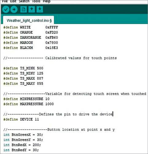
Arduino Weather Station Code
The code (weather_light_control.ino) for this project is written in Arduino programming language. The project requires specific libraries for DHT22 and a touch-screen display such as DHT.h, SPFD5408_Adafruit_GFX.h, SPFD5408_Adafruit_TFTLCD.h, and SPFD5408_TouchScreen.h
One of the challenges in the project is calibrating the touch points in the touch-screen display.
Depending on the model and size of the touch-screen display, you need to calibrate the x and y coordinates. The calibrated values in the code used by the author are shown below.
Download Source Code
Weather Monitoring System Working
After uploading the code to the Arduino Uno board, mount the TFT touch-screen on top of the Arduino board through the header pins already provided on the Arduino board. You can carefully place it with a slight push on the touch-screen from the top. Ensure the correct positions of the male header pins from the touch-screen display are inserted into the corresponding female pins on the Arduino board.
Now you can connect the board to the USB port of your PC/laptop or use a 9V-12V DC supply.
The working of the circuit is simple. After uploading the code to the Arduino Uno board and connecting all the components, as shown in the circuit, switch on the circuit. You will see the main panel on the TFT touch-screen, as shown below. Touch the Device Control option using a stylus or your fingertip, to turn on or turn off the appliance/device such as a tube light or air-conditioner. Otherwise, touch on the Weather Station option to check the current temperature and humidity.

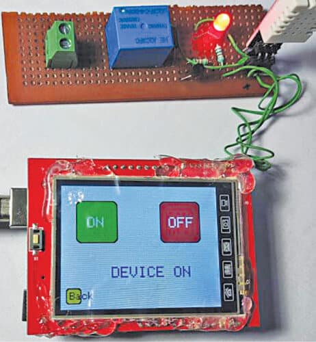
To control the device, such as the light or air-conditioner connected across the relay, touch the ‘Device Control’ option. There are on and off buttons in the Device Control section, as shown in Fig. 8. When you touch the ‘on’ button, the LED will glow and at the same time the electrical device/appliance connected across the relay will turn on. Touch the ‘off’ button to turn it off.
If you touch the ‘Weather Station’ option, it will take you to another screen, as shown below. You can see the current humidity and temperature values captured by the DHT22 sensor.
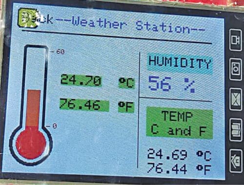
The humidity here is basically the relative humidity expressed in percentage, which represents the amount of water vapor in the air at a given temperature compared with the maximum possible water vapor at that same temperature. Here the temperature values are read in both °C and °F units. So, no conversion is required.
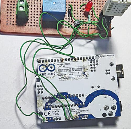
Construction and Testing
The circuit can be assembled on a breadboard or Veroboard. We used a 10x3cm Veroboard to mount the relay, sensor, transistor, LED, 2-pin terminal connector (optional), and two resistors.
Since most of the Arduino pins are used by the TFT touch-screen display, you need external wires to solder at digital pin 11 of Arduino for the relay driver and analog pin A5 for the DHT22.
You also need to solder 5V and GND pins of Arduino for power supply to the Veroboard. If you are using the DHT22 sensor instead of the module, make sure you connect a 5-kilo-ohm pull-up resistor at its output pin, otherwise, you may not get the correct temperature and humidity readings.
Also, note that some 6cm TFT touch-screen displays may not work. So, it is recommended to use the model that we used here. If you want to control an appliance like a cooler or AC, you need to replace the sugar-cube relay with a high-power relay having contact ratings above 16A.
So this is how you can make your own touchscreen weather monitoring system using Arduino.
If you have any doubts or face any issues/errors while making this project, please feel free to ask in the comment section below.