


 Op-amps require dual-polarity supply for proper operation. When working with battery supply, it becomes difficult to get dual power supply for the op-amps. Presented here is a simple circuit that provides ±5V from a 9V battery.
Circuit and working
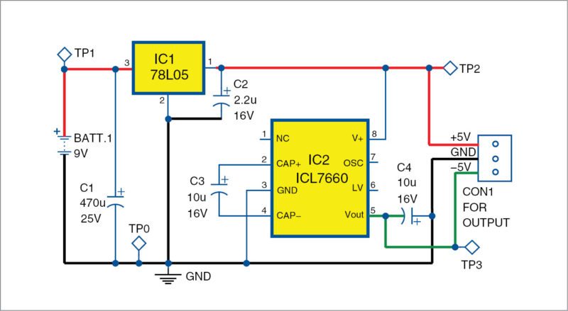
 The circuit diagram for the ±5V supply from a 9V battery is shown in Fig. 1. It is built around 9V battery (BATT.1), voltage regulator IC 78L05 (IC1), CMOS voltage converter ICL7660 (IC2) and a few other components.
Voltage regulator IC1 converts 9V battery input into regulated 5V. This 5V output from IC1 is given to pin 8 of IC2. IC2 and capacitors C3 and C4 form the voltage inverter section that converts +5V to -5V. Converted -5V supply is available at pin 5 of IC2. Converted ±5V supply is thus available at connector CON1.
Construction and testing

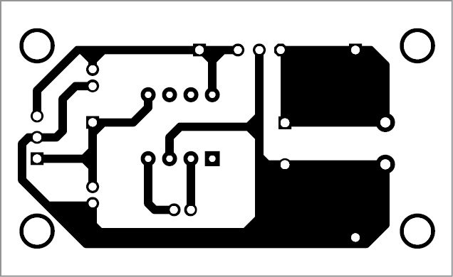
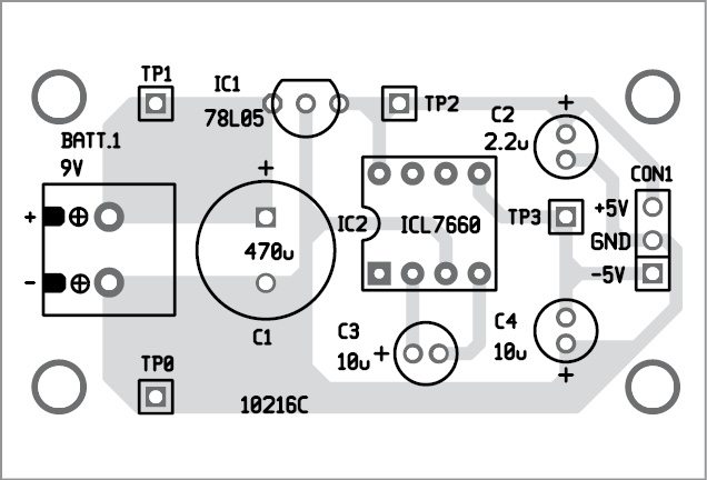
An actual-size, single-side PCB for±5V supply from 9V battery is shown in Fig. 2 and its component layout in Fig. 3.
Assemble the circuit on the PCB and enclose it in a water-proof box. Battery BATT.1 should be enclosed in the box. Fix CON1 on the front or rear side of the cabinet, so that you can use the ±5V easily.

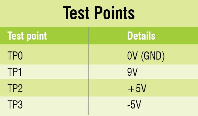
Before using the circuit, verify the test points given in the table to ensure proper working of the circuit.
Download PCB and component layout PDFs: click here
A. Samiuddhin is B.Tech in electrical and electronics engineering. He has been an electronics hobbyist since ninth standard.
This article was first published on 14 June 2016 and was recently updated on 4 February 2019.

how to convert those pdfs to the pcb layout ?
does it cost a lot to make this kind of project?
What software did you use for designing the above circuit?