Here is a low-cost, pressure sensitive alarm. The alarm uses a home-made pressure sensor, which works as a variable capacitor using two copper-clad boards and a piece of sponge in between them.
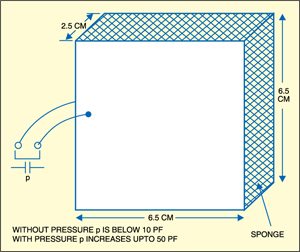
To make the pressure sensor (variable capacitor C1), take two 6.5×6.5cm2 ordinary copper-clad boards used for making PCBs. Apply varnish or green mask on the copper material. Place about 2.5cm thick soft sponge between the copper-clad boards and fix them with an insulation tape as shown in Fig. 1. Solder ordinary insulated flexible wires to copper plates on both the cladded boards. These wires are used for connecting the pressure sensor to the input of the alarm circuit.
Pressure sensitive alarm circuit
Fig. 2 shows the circuit of the pressure sensitive alarm. When no pressure is applied to the sensor plates, capacitance of the home-made sensor is less than 10 pF and IC 555, wired as an astable multivibrator, does not function. When pressure is applied to the sensor, the distance between the copper-clad boards reduces and the capacitance of the sensor may be raised up to 50 pF, depending upon the distance between the two copper-clad boards. Thus the sensor works as a variable capacitor in IC 555-based astable multivibrator.

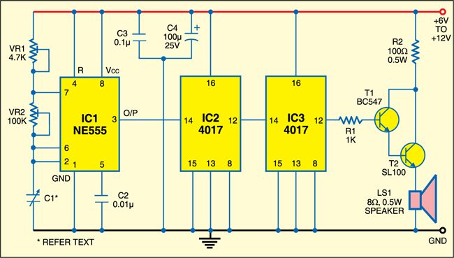
IC 555 oscillates at about 350 kHz, which is not audible. This output signal is given to two 4017 decade counters. Decade counter IC2 converts the 350kHz signal into 35kHz signal, which also is not audible. The 35kHz output of IC2 is fed to decade counter IC3, which converts it into an audible tone of 3.5 kHz. These frequencies can be varied using preset controls VR1 and VR2 along with the pressure on the sponge between the copper-clad boards.
The 3.5kHz audio frequency signals from IC3 are amplified by transistors T1 and T2 to drive the loudspeaker, which produces a sharp audible tone.
Circuit Applications
You may keep this home-made pressure sensor under the door mat at the entrance of your home and the speaker at a suitable location in your house. When someone steps on the mat, the alarm will sound. A 6-12V DC supply can be used to power the circuit.
Constructions & testing
Assemble the circuit on any general purpose PCB and enclose in a suitable cabinet. Connect the sensor and the loudspeaker through flexible wires. You can experiment with different sizes of pressure sensors for different tones and loudness.
The article was first published in March 2008 and has recently been udpated.