


We have witnessed a rapid inclination towards automation lately. Considering some of the factors such as time consumption, affordability, feasibility and convenience, automation has enhanced our standards of living in numerous ways.
Abiding by this notion, we are presenting an Automatic curtain opener model using LDR. It does the task of folding and unfolding of the curtain as per the light intensity outside the window. It is an automatic process and the light intensity is sensed by LDR in the circuit.
| Component Name | Value | Quantity |
| LDR | 2 | |
| 555 Timer IC | 2 | |
| Transistor | Q1BC547 | 2 |
| DC Motor | 12V | 1 |
| Resistor | 330 ohm | 1 |
| 470 ohm | 1 | |
| 1K | 1 | |
| 100K | 1 | |
| Power supply (Battery) | 9-12 V | 1 |
| Capacitor | 820nF | 2 |
| 0.01uF | 2 | |
| 2 channel Relay Module | 1 | |
| LEDs | Green | 2 |
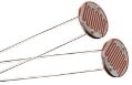
Light Dependent Resistor (LDR):
An LDR is a light sensitive electronic component. The resistance changes with the intensity of light incident on it. Values of the resistance of the LDR ranges over many orders of magnitude. The value of the resistance falls as the level of light increases.

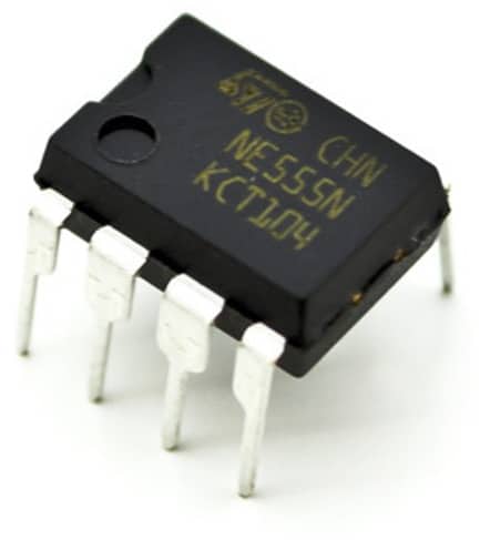
555 timer IC:
The 555 timer IC is a precision timing device which can act as either a simple timer to generate single pulses or long time delays, or as a relaxation oscillator producing a string of stabilized waveforms of varying duty cycles from 50 to 100%. The basic 555 timer gets its name from the fact that there are three internally connected 5kΩ resistors which it uses to generate the two comparators reference voltages.
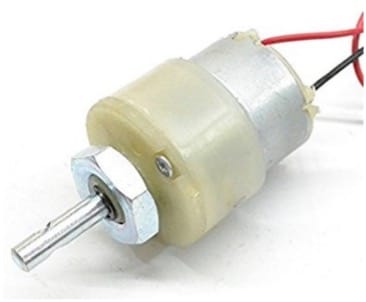
DC Motor:
When a magnetic field and an electric field interact, a mechanical force is produced. The DC motor or direct current motor works on that principle. This is known as motoring action. An electric motor operated by DC (direct current) is known as a DC Motor. A DC motor converts DC electrical energy into mechanical energy.
Block diagram
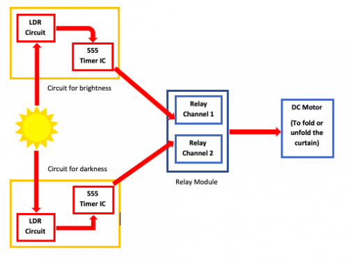
Working
- Two separate LDR circuits are used here. One senses the darkness and other one is for light sensing. Deploying two separate circuits, one for sensing the light and the other for the darkness, ensures the proper reversal of rotation of the motor in one of the cases.
- The output of the respective LDRs are connected with two timer ICs set with time delays sufficient to fold and unfold the curtain.
- Light sensing LDR circuit is inactive when exposed to darkness and vice-versa.
- Output of the respective timers reaches the motor via 2 channel relay module.
- Motor runs for the time period determined by the delay provided in each of the cases and the curtain moves accordingly.
- The time delay for each of the cases can be set by using different values of resistor and capacitor in the timer circuit. Thus, the time delay can be determined using the following formula:
T = 0.69 x R x C
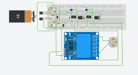
Schematic: (made using Fritzing software)
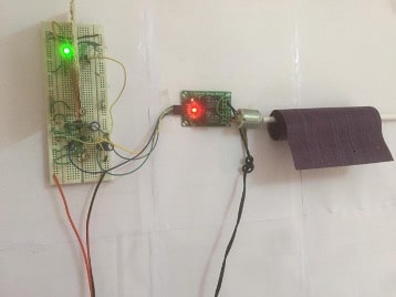
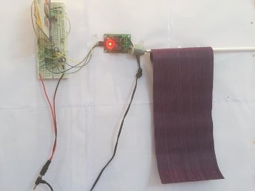
Actual Photos of the Prototype:
This article is a part of the Top 10 LDR-based Electronics Projects. If you want to read more projects based on LDRs can go through this article.
Project executed by Asmita Mukhopadhyay with Prof. Geetali Saha, Department of Electronics and Communication, GCET, Gujarat, India.
give me the code
No Source code is needed for this project