


 Here is a meter to measure the human heart rate. The pulses are picked up around the wrist (just as it is examined by the doctor) using a condenser microphone fastened with a suitable belt.
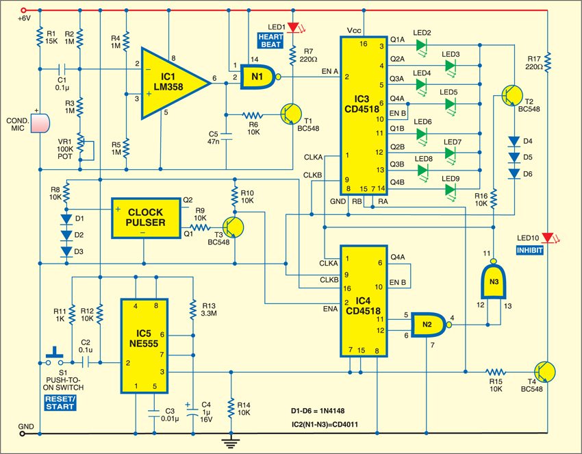
The circuit is built around a low power audio amplifier LM358 (IC1), NAND gates CD4011 (IC2), dual up counters CD4518 (IC3 and IC4), timer IC NE555 (IC5), clock pulser, four npn transistors BC548 (T1-T4) along with some discrete components. The human pulse rate is indicated in binary-coded display format on LED2 through LED9.
To know the heart rate one has to fasten the condenser microphone properly to the wrist and press the RESET/START switch S1 momentarily. The counters built around IC3 and IC4 are inhibited for some time. The inhibit LED10 glows for a brief period. As soon as the inhibit LED10 goes down, the counting starts. The display (LED2 through LED9) remains off during counting of pulse rate to save power during battery operation.

The divider counter IC4 counts for one minute after which it is disabled by the logic of the circuit. The one-minute timing is derived from common quartz clock pulser, which can be easily borrowed from any old quartz clock. The clock pulser provides two outputs—Q1 and Q2—which drive the coil of the quartz clock. One of the outputs (Q1) of the clock pulser is used to obtain the required timing of one minute (60 seconds, which corresponds to 30 counts). Each output gives a pulse at every two seconds. Q1 is fed to pin 2 of IC4 through transistor T3. At the end of one minute, the divider counter built around IC4 and the rate counter built around IC3 are inhibited. The pulse rate count is displayed on the LEDs powered by transistor T2, which becomes conductive at the end of one minute through NAND gates N2 and N3.
The preset VR1 associated with the audio amplifier circuit built around IC1 has to be adjusted to get clear heart beat signals. The condenser microphone should be placed on the pulsating vein near the wrist. After the condenser microphone is fastened with a suitable belt or rubber band, you can take a fresh reading. For this you have to press the RESET/START switch S1 momentarily.
Assemble the circuit on a general purpose PCB and enclose in a suitable cabinet. Fix the 2-pin connector on front side of the cabinet in such a way that condenser microphone can be placed firmly on the skin of the lower wrist to get a good signal, preferably where the pulse can be easily sensed. Keep the 6V battery inside the cabinet. Fix the display LEDs in BCD format to read the pulse rate easily.
Im confused about how to give the pulse as input, could you please explain.