


 This project demonstrates how you can build a real-time clock (RTC) with a temperature display using Arduino, DS3231 RTC chip, and SSD1306 OLED display (128×64 pixel).
DS3231 RTC chip is more accurate than DS1307 and also has a built-in temperature sensor. It keeps the time running even when the main power source is down. It uses the I2C interface to communicate with the master device (microcontroller), in this case the Arduino.
DS3231 and SSD1306 OLED share the same I2C bus, but the microcontroller can communicate with only one of them at a time, depending on the address sent. The DS3231 RTC address is 0×68, and the SSD1306 OLED address is 0×3C.

Fig. 1 shows the author’s prototype, and Fig. 2 shows the circuit’s block diagram.
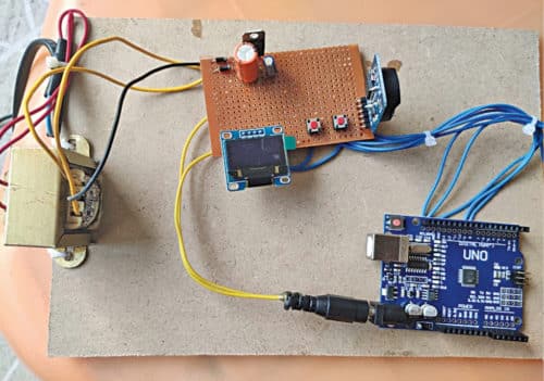

Circuit and working
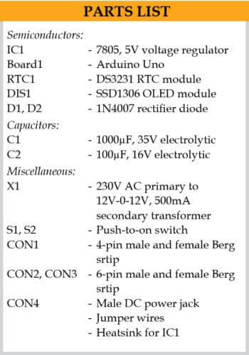
Circuit diagram of the Arduino real-time clock with temperature display is shown in Fig. 3. It is built around Arduino Uno (Board1), 5V regulator 7805 (IC1), 2.4cm SSD1306 OLED display (DIS1), DS3231 RTC module (RTC1), and a few other components.

SSD1306 OLED display
OLED (organic light-emitting diode) is a flat light emitting device developed with organic thin films that are connected in series between two electric conductors. The OLED display used in this project is shown in Fig. 4. It has improved image quality, full viewing angle, high brightness, better contrast, wide colour range, and low power consumption. It is more efficient and reliable as compared to a simple LCD display.
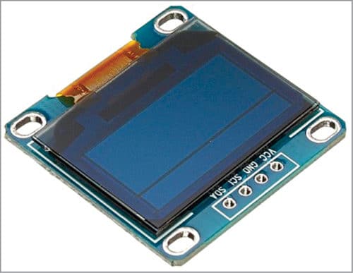
It is mainly used in such digital display devices as computer monitors, mobile phones, hand-held video games, and television screens. It is easily available in the market as well as online stores.
The display module connects to Arduino using four wires—two for power and another two for data— making the wiring very simple. The data connection is based on the I2C (inter-integrated circuit) interface, which is also known as TWI (two wire interface).
DS3231 RTC module
The DS3231 module is a low-cost, highly accurate real-time clock that can maintain time in hours, minutes, and seconds as well as the day, month, and year information. It has automatic compensation for leap years for and months with less than 31 days.
The module can work on either 3.3V or 5V, which makes it suitable for many development platforms or microcontrollers. The battery input is 3V, and a typical CR2032 3V battery can power the module and maintain the information for more than a year. The DS3231 module (front and back) used in this project is shown in Fig. 5.
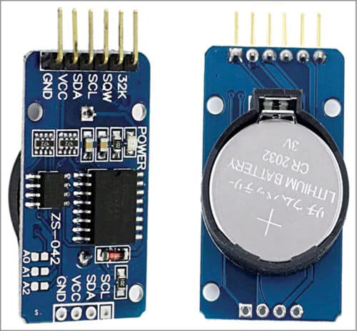
The I2C communication protocol used in the module makes connections to the Arduino board very easy. All we need are four pins: VCC and GND pins for powering the module, and SDA and SCL pins for I2C communication.
Power supply
The regulated power supply is designed with a full-wave rectifier built around 1N4007 diodes (D1 and D2), two capacitors (C1 and C2), 5V voltage regulator 7805 (IC1) and 230V AC primary to 12V-0-12V, 500mA secondary step-down transformer (X1). In the project, two power supplies are required: 12V DC for Arduino Uno power jack, and 5V for DS3231 RTC and SSD1306 OLED module.
Arduino Uno
The heart of the project is the Arduino Uno R3 board, which is based on ATmega328/ATmega328P microcontroller. It has 14 digital input/output (I/O) pins, six analogue inputs, 32k flash memory, 16MHz crystal oscillator, USB connection, a power jack, an ICSP header, a reset button, among others. It can be programmed using Arduino IDE software.
In the circuit, there are two push buttons: S1 for setting and S2 for mode change. These are used for setting the time and date of the real-time clock. The ground connection of Arduino needs to be connected to ground connections of RTC1 module and display DIS1 module.
Construction and testing
After making all the connections, test the working of the circuit by pressing the mode button (S2), and then release it. The cursor on display will flash on the day-of-week field. Press and hold the set button (S1) to advance the day of the week to the next day at 5Hz rate, or do a short press to advance to the next setting.
Press and release the mode button (S2) to advance the cursor to the month field. Press and hold the set button (S1) to scroll through the months quickly, or do a short press to advance to the next setting. Press and release the S2 button to advance the cursor to the date field. Press and hold the S1 button to scroll through the dates quickly, or do a short press to advance to the next setting.
Note that the RTC chip knows the correct number of days in each month. Press and release the S2 button to advance the cursor to the year field. Press and hold the S1 button to scroll through the years quickly, or do a short press to advance to the next setting. Valid ranges are 2000 to 2099. The RTC chip keeps track of leap years automatically. When you first power up the clock, the date will be January 1, 1900. Just advance the year to the correct value.
Press and release the S2 button to advance the cursor to the hour field. Press and hold the S1 button to scroll through the hours quickly, or do a short press to advance to the next setting. The clock uses only 24-hour mode in the project. Press and release the S2 button to advance the cursor to the minutes’ field. Press and hold the S1 button to scroll through the minutes quickly, or do a short press to advance to the next setting. Press and release the S2 button to advance the cursor to the seconds’ field. Press S2 button momentarily to reset the seconds to zero, or hold the button to freeze the seconds at zero and release to synchronise with an external time source. DS3231 RTC chip has an inbuilt temperature sensor.
Thus, it gives time, date, and year along with temperature readings (refer Fig. 6).

Software
Circuit operation is controlled by the software program (main_code.ino) loaded into the internal memory of Arduino Uno. The program implements all the required functionalities.
The program/sketch is written in the Arduino programming language. Arduino IDE version 1.8.11 is used to compile and upload the program to the Arduino board.
In this project, the following header files are required in the main_code.ino for programming:
#include <wire.h>. This header file is especially required for I2C protocol devices for faster communication. In this project, the two I2C devices are SSD1306 OLED display and DS3231 RTC module. (This header file is already included in the latest Arduino IDE.)
#include <Adafruit_GFX.h>. The header file Adafruit Graphical library is used to generate different types of graphics like square, triangle, black and white colour inversions, star symbols, and images in .bmp formats. In this project, different font sizes and special symbols notation for temperature units (degrees centigrade) are used.
#include <Adafruit_SSD1306.h>. This header file is used to communicate with the SSD1306 display using address mapping. The SSD1306 display having 128×64 pixel size can display the data up to eight pages alternately. Access each page by using three address lines. The selection of address lines, data and commands are very easy using Adafruit_SSD1306 header file.
The Arduino code (main_code.ino) requires two external libraries: Adafruit-GFX-Library-master.zip and Adafruit_SSD1306-master.zip. You need to include them in Arduino IDE before compiling and uploading the code to the Arduino board.
A PCB layout for Arduino real-time clock with temperature display is shown in Fig. 7 and its components layout in Fig. 8.
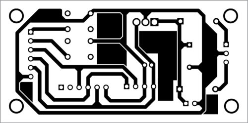
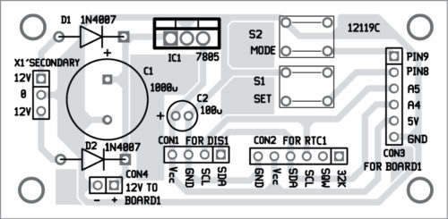
Download PCB and Component Layout PDFs: click here
Download Source Code
After assembling the circuit on the PCB, connect Arduino Uno pins to PCB using jumper wires. Do not forget to upload the source code into the Arduino Uno board before wiring. The circuit works with 230V AC mains using the transformer (X1), as shown in the circuit.
Also check: best Arduino projects.
Pamarthi Kanakaraja is an assistant professor (R&D cell) at KL University, Vaddeswaram, Guntur district, Andhra Pradesh.
Dr K Sarat Kumar is a professor at KL University. He is also one of the technical members from KL University, providing technical support on RF antenna designs to NARL (National Atmospheric Research Laboratory). He has 22 years of work experience in RF antenna designing, testing and simulation in a real-time environment.

source code not available
Hi Mahesh, the Source Code is present at the end of the project. You can also download the Source Code from here.
There isn’t any source contained in the links given, only PCB layouts
Hi Saeed, please refresh the page and retry.
how source code puts in the Aurdino?????
Kindly elaborate on your query.