


 This simple circuit can be used to count the number of cars entering a parking lot.
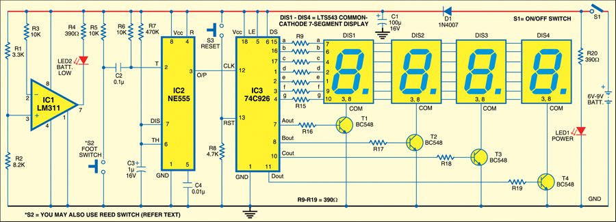
The circuit is built around comparator LM311 (IC1), timer 555 (IC2), 4-digit counter IC 74C926 (IC3), four LTS543 seven-segment displays (DIS1 through DIS4), four npn transistors BC548 (T1 through T4), a foot switch S2 and a few discrete components.
In place of the foot switch, you can also use a normally-open-type reed switch. Mount the reed switch on the gate along with a magnet such that when someone opens the gate, the switch closes momentarily to provide a clock pulse for IC3 from timer IC2. The foot switch or reed switch plays an impotant role in timer NE555 operation and hence counting of the cars, provided mains power switch S1 is ‘on.’
LED1 indicates that power to the circuit is switched on and the circuit ready to count. The circuit has a facility to check the battery voltage. At normal voltage (6V to 9V), LED2 remains off and LED1 glows. When the voltage goes below 4V, LED2 glows to indicate that the battery requires replacement or recharging.
Install the foot switch on the vehicle track at the entrance gate such that when any vehicle passes through the gate, the foot switch is pressed or pushed down momentarily by the wheel of the vehicle. This provides a trigger pulse to pin 2 of timer IC2, which is configured in monostable mode. The time period of the monostable is determined by timing components (resistor R7 and capacitor C3). The pulse output at pin 3 of timer IC2 acts as the clock pulse for counter IC3.
IC3 (IC 74C926) consists of a 4-digit counter, an internal output latch, npn transistor output sourcing drivers for common-cathode 7-segment display and an internal multiplexing circuitry with four multiplexed outputs. A maximum of 9999 digits can be counted and shown on DIS1 through DIS4. A high signal at reset pin 13 of IC3 makes all the outputs zero. So the display shows 0000.
Working of the circuit is simple. To start counting the number of vehicles passing through the gate, first press reset switch S3 momentarily. The display will show 0000. Now press switch S2 momentarily to trigger IC2 for a preset time. The counter increments and generates the code to display the count on the seven-segment displays (DIS1 through DIS4). The display shows the count in incremental order.
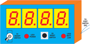
Assemble the circuit on a general-purpose PCB and enclose in a cabinet leaving enough space for the battery. Mount switches and displays on the front panel of the cabinet. Place the unit (shown in Fig. 2) at a suitable place so that the count on its display can be read easily. Install the foot switch on the vehicle track.
The circuit works off 6V-9V DC, which you can get either from four AA-size (or six AAA-size) cells in a battery holder or a 9V PP3 battery. You can also use a 6V-9V adaptor in place of the battery.

do you have a schematic diagram on tinkercad of this project?? please email me [email protected] thank you so much