


 79xx is a widely known series of low-cost, fixed-negative-voltage regulators. These integrated circuits are available with output current of 100-150 mA (L series), 0.4-0.5A (M series), up to 1A (standard series), etc. They can be used in many applications other than regulators, audio power amplifier being one of them.
As shown in the circuit diagram, a simple stereo audio amplifier is built around two 7905 negative-voltage regulators (IC1 and IC2) and a few discrete components. The 7905 IC (a -5V regulator) used here is readily available. However, the circuit will also work with other 79XX regulators if appropriate power supply is used. Both channels shown in the diagram are identical. Hence the description below is only for the first channel. The quality of the output signal is within acceptable limits.
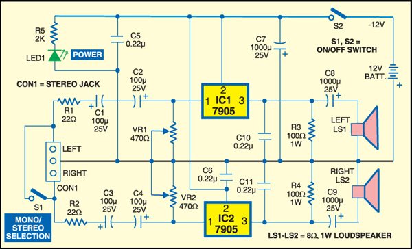
Regulator IC 7905 works as an amplifier for the voltages applied to common pin2 (Ground or GND). The minimal voltage drop over the standard 7905 is around 2V and it depends on the output current. Feedback resistors in the IC set the gain of the channel internally. The amplifier is a class-A audio amplifier. The regulator IC produces the negative output signal.

Resistor R3 provides the positive signal. It limits the maximum output current of the regulator during the negative half period of the amplified sinusoidal signal. The minimal applicable value of R3 for the regulator 7905 is 8.2 to 10 ohms per 5W.
Optimisation of the value of R3 depends on the output voltage of the regulator, negative power supply (–5V) and load resistance of loudspeaker (LS1). If the required output current for LS1 is below 100 mA, the value of resistor R3 can be 33 to 51 ohms per watt.

Normally, the load resistance of the loudspeaker should be higher than of R3 in order to obtain a large peak-to-peak amplitude. But this can be neglected in order to obtain lower power dissipation on R3 and the IC.
The circuit works with any load resistance (R3 in parallel with LS1 as the load) under the condition that the regulator is not overloaded with current and power dissipation. However, it is preferable to use a loudspeaker with a high resistance (8 ohms, 16 ohms or more). The amplifier works well with low-impedance headphones having a resistance of 24 to 32 ohms. The voltage difference between the ground pin of 7905 and the output pin is fixed internally.
The input resistance of the amplifier is relatively low and depends on potentiometer VR1 and input resistance of the ground pin. Practically, any stereo output capable of driving 24- or 32-ohm headphones and loudspeakers can drive the input of the stereo amplifier with 7905. If VR1 is removed, the amplifier will still work but there will be more distortion. Therefore potentiometer VR1 is used to provide sufficient variable audio signal.
The values of output capacitors C10 and C11 are usually between 0.1 µF and 1 µF. A small resistance can be connected in series with them if needed.
S2 is the on/off switch. Switch S1 is for mono/stereo selection. When switch S1 is closed, the amplifier works as a two-way mono amplifier. If S1 is open, the amplifier works as a stereo amplifier.
The circuit is powered by a 12V battery. The positive terminal of the battery is the common node. The negative terminal is connected to pin 2 of IC1, which is the –12V supply line. The maximum operating voltage can be up to –35V.
If no input signal is applied, the DC voltage on the output of the regulator 7905 should be around –5V, which depends to some extent on the value of VR1. The maximum output current of 7905 can be up to 1A and the maximum power dissipation is up to 15W. IC 7905 has internal thermal protection.
Assemble the circuit on a general-purpose PCB and enclose in a suitable cabinet. Fix the stereo female jack on the front panel and speaker to the rear side of the cabinet, and the 12V battery inside the cabinet. Fix LED1 and switches S1 and S2 too on the front panel of the cabinet. Mount the regulator IC 7905 on a heat-sink with thermal resistance below 15°C/W. The metallic part on the case is internally connected with the input pin of the regulator.