


Unveiling a low-cost, low-power handheld or wearable solution, this demo board allows designers to create devices capable of measuring heart rate and blood oxygen levels.
Incorporating heart rate and blood oxygen level measurement capabilities is becoming increasingly prevalent in consumer products. These measurements can now be conducted using pulse oximeters designed for home medical use and integrated into wrist-worn fitness activity trackers. A pulse oximeter is a non-invasive device for gauging a person’s blood oxygen saturation level and heart rate. In our Pulse Oximeter Demonstration, LEDs emit two wavelengths of light through a finger to a photodetector. Through this process, the demonstration assesses changing absorbance at each wavelength, processes the data, and applies filtering techniques to determine blood oxygen saturation levels and heart rate.
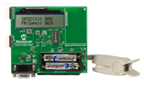
Microchip’s pulse oximeter reference design demo board helps designers develop a low-cost, low-power handheld or wearable pulse oximeter with a user interface capable of measuring heart rate and blood oxygen level. It can be used to start the development of a hospital or clinical pulse oximeter design, but it can also be used as a starting point for the development of a wearable activity tracker design that can measure heart rate and blood oxygen level. The device efficiently measures heart rate and per cent blood oxygen saturation level, utilising a dsPIC33FJ128GP802 equipped with a 513th-order digital-FIR bandpass filter created through our Digital Filter Design Tool. This advanced filtering mechanism eliminates the necessity for a costly Analog front-end (AFE) component, contributing to a low overall Bill of Materials (BOM) cost. Integrating an Integrated Pulse-Width Modulation (PWM) module seamlessly drives the LCD. The design incorporates an MCP1640 boost regulator, MCP4728 DAC, and the MCP6002 dual op-amp to ensure reliable and accurate power management and signal conditioning, enhancing the device’s overall performance.

The system’s operating range spans up to 40 Million Instructions Per Second (MIPS) at a voltage range of 3.0 to 3.6 volts. It maintains functionality within a temperature range of -40ºC to +150ºC, supporting Direct Current (DC) operations up to 20 MIPS and within -40ºC to +125ºC for DC operations up to 40 MIPS. The device features an efficient Direct Memory Access (DMA) system, boasting an 8-channel hardware DMA and a substantial 2 Kbytes dual-ported DMA buffer area (DMA RAM) for data storage. In the realm of timers, capture, compare, and pulse-width modulation (PWM), the system accommodates up to five 16-bit and two 32-bit timers/counters, with one timer configured to operate as a Real-Time Clock using an external 32.768 kHz oscillator. Additionally, the device incorporates power management capabilities, including an on-chip 2.5V voltage regulator and the ability to switch between clock sources seamlessly in real time for optimal performance.
Microchip has extensively validated this reference design, providing comprehensive resources such as a Design Guide, Demo ‘C’ source code, application notes, and schematics. Please visit the company’s website for additional information about this reference design. To delve deeper into the intricacies of this design, you can click here for an in-depth exploration.