
GPS tracking is one of the most important technologies in today’s world. From parcel updates to navigation and many different fields, we rely on GPS.
However, if we want to track smaller items such as baggage or monitor the location of children, or if we intend to monitor someone discreetly, we often require a compact and inconspicuous device that can be easily attached without occupying much space.
Today, we will design the smallest GPS tracker that you can use as a key ring or attach as a small tag to bags to track children, affix to the necks of animals, or integrate with vehicles, parcels, or individuals for tracking purposes.
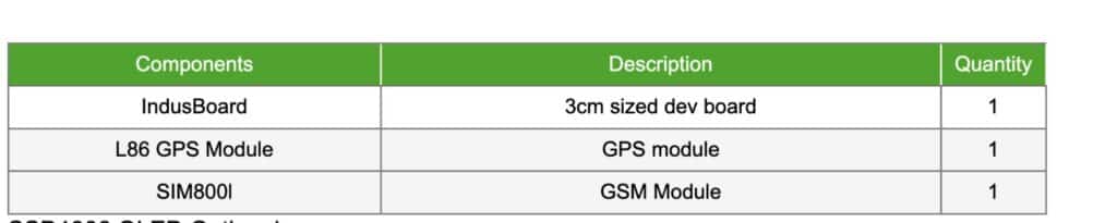
In our design, the primary requirement is to maintain a compact size within 3cm. Therefore, we opted for the Indusboard Coin as the base.
Additionally, to ensure the GPS unit remains small, we selected the L86 GPS module, measuring only 1.5 cm and equipped with an integrated GPS antenna.
POC Video Tutorial In English
POC Video Tutorial In Hindi
For transmitting data via GSM, we incorporated the SIM800l module, which operates on the 2G band. However, if higher network speeds are desired, it’s possible to substitute this with a 4G or 5G GSM module.
Bill of Material
DIY Smallest GPS Tracker – Design
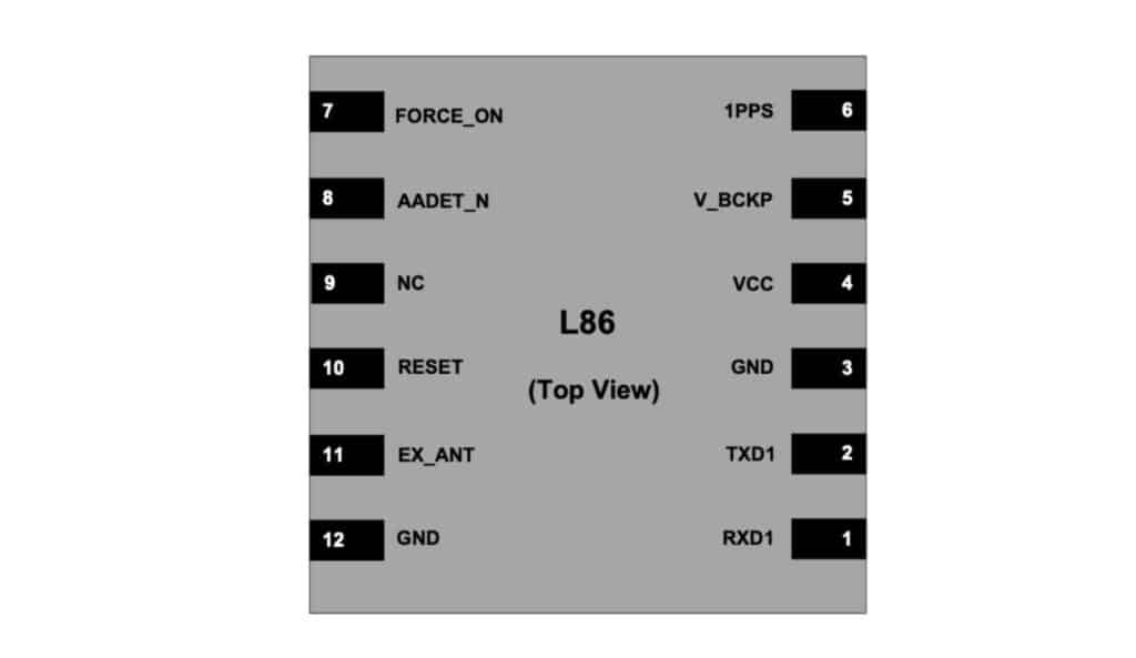
In our design process, we decided to use the L86 GPS module. It communicates through a serial port with a speed of 9600 baud. The Indusboard, which we’re using, supports both software and hardware serial.
We can configure any pins for this purpose, but by default, pins 43 and 44 serve as RX and TX serial pins on the board. So, we’re using this hardware serial connection for the L86 GPS.
The L86 GPS module needs power in the range of 2.8V to 4V, and it typically uses around 100mA when it’s working. Luckily, the board we’re using already has a pin that can handle this power. So, we’re connecting the GPS module to the 3.3V and GND pins on the Indusboard for power.
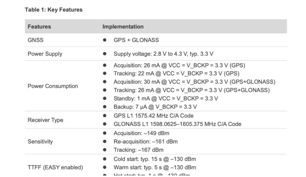
The GPS module comes with an RTC backup power pin. This feature, according to the datasheet, allows the Real-Time Clock (RTC) to keep track of time even if the main power is disconnected. Typically, you can attach any 3.3V coin cell battery to this pin for backup power.
However, in our design, we decided to simplify things by using the same voltage source for the main power and the RTC backup. So, we’re connecting this RTC backup power pin to the same 3.3V source that powers the GPS module.
Next, we incorporated the GSM module into the design. Most GSM modules, including the SIM800l, SIM808, and others, also utilize serial communication. For this purpose, we designated pins 43 and 41 as the serial pins.
Like the GPS module, we powered the GSM module using the same 3.3V and GND power supply of the board.
Additionally, if you desire to view network status, receive SMS and access location coordinates such as latitude and longitude, you have the option to include the SSD1306 OLED display.
However, it’s important to note that this addition will increase both the bill of materials and power consumption of the device. Although not included here, our design accommodates this feature by providing the necessary connections for the SSD1306 OLED display.
Now you can solder all the components according to the circuit diagram. (Fig 4).
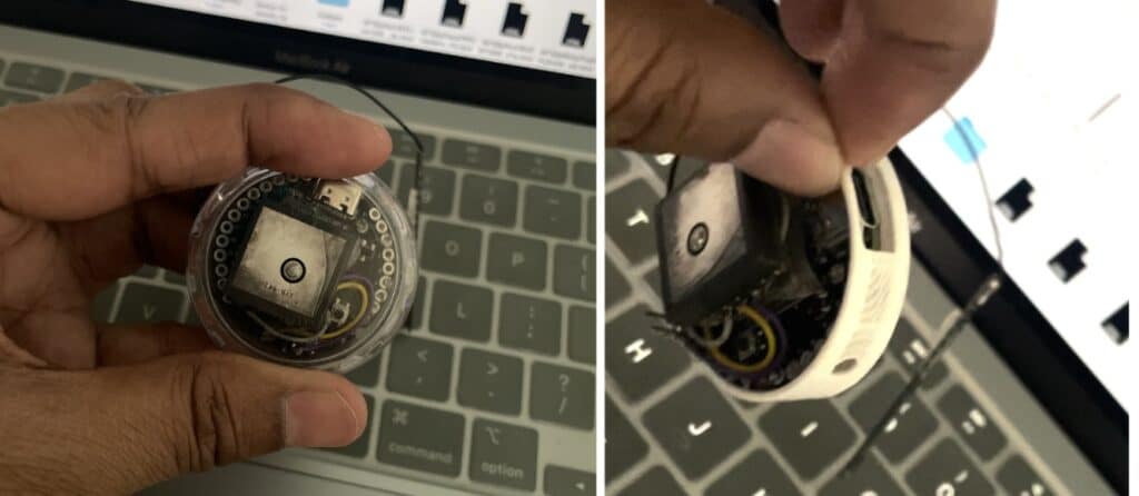
After soldering the components together, we’ll place the GSM module and secure it either on the top or bottom of the board. Similarly, we’ll position the GPS module in the same manner as depicted in Figure 5 and Figure 6.
Now you can design the keyring and tag case over the device and attach it anywhere to use it.
Code for GPS Tracker
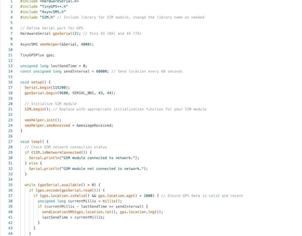
Firstly, we’ll install the Async message library. Then, we’ll define the serial pins and baud rates for both the GPS and GSM modules. The default baud rate for GSM is 4800, and for GPS, it’s 9600.
Next, we’ll create a function to retrieve the GPS location and send it to the predefined number at a one-minute time interval. You have the flexibility to adjust this time interval according to your requirements.
Additionally, you can implement features such as responding with a location map link when a specific message is received by the device. The code offers various customization options to tailor it to your needs.
Testing Smallest GPS Tracker
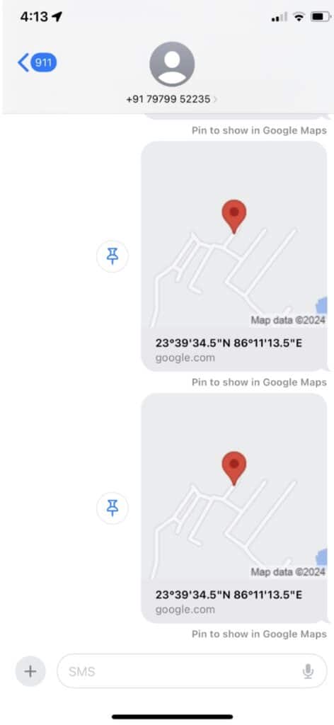
Once the device is powered using a 3.3V rechargeable battery, insert a SIM card with a message pack into the GSM module. After a few minutes, when the SIM module establishes a connection with the network provider, it begins sending real-time location updates to your phone.
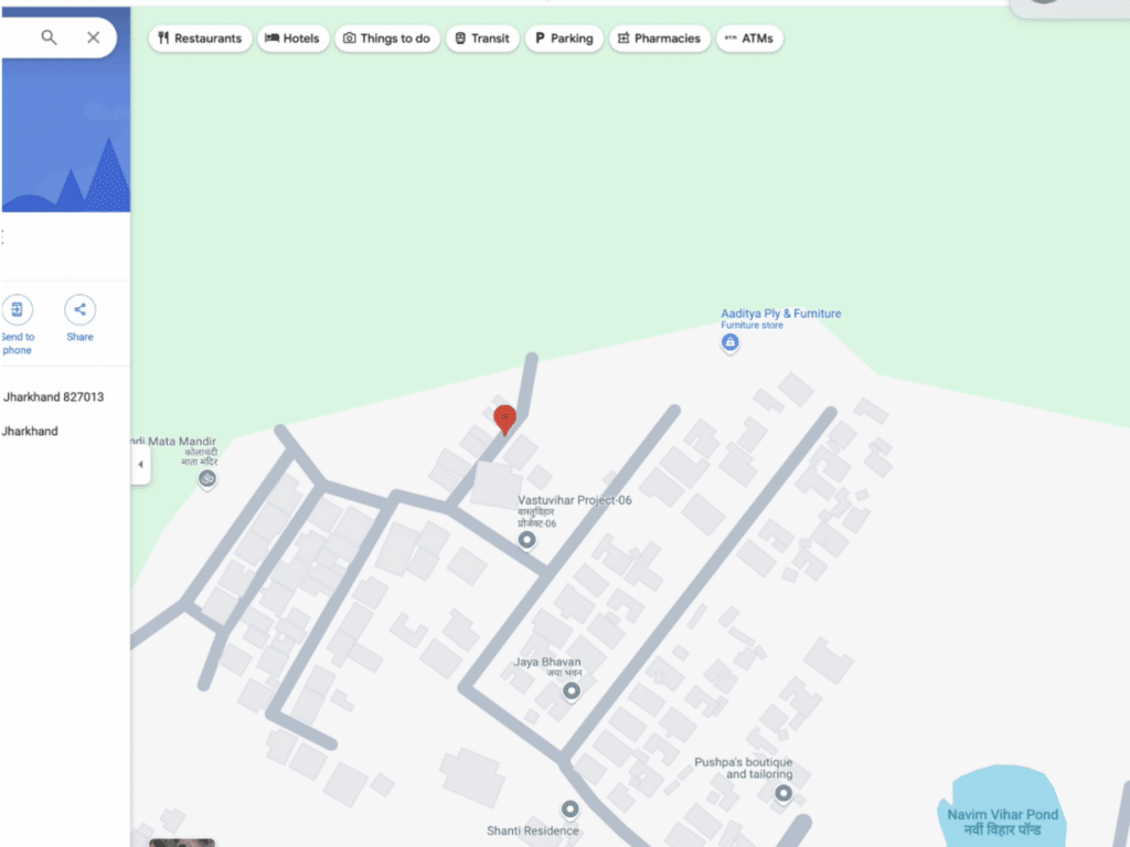
When you tap on the link received, you can view the location on Google Maps, providing you with accurate tracking information.