T his smart cellphone holder makes sure that you don’t forget to carry your mobile phone. Fitted in the car, it keeps searching for the mobile phone within the holder using infrared (IR) rays and alerts you through a flashing LED when it doesn’t find one. You can attach the circuit to your existing cellphone holder or, with a little skill, construct one as per your requirement.
Smart Cellphone Holder Circuit
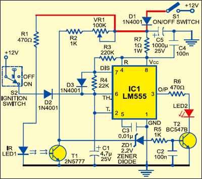
The circuit, wired around IC LM555 (IC1), derives power from the 12V DC automobile battery. Diode D1 is an accidental wrong-polarity input guard. Resistor R7 limits the inrush current to IC1.
Circuit operation
When power is applied to the circuit, the low-frequency astable multivibrator built around IC1 is activated and LED2 at its output pin 3 flashes briefly.

When ignition switch S2 is flipped to ‘on’ position, the +12V DC from the car’s battery disables the astable multivibrator via diode D2 and LED2 turns off.
When the ignition is turned off and the mobile phone is in its holder, LED2 again starts blinking. In case the cellphone holder is empty, IR rays from IR LED1 fall on phototransistor T1 and it conducts to pull the base of LED driver transistor T2 towards ground to disable the visual indicator (LED2).
If you’ve forgotten to carry your cellphone, LED2 fitted in the cellphone holder will stop flashing to indicate that the mobile phone is not in the cell holder of the case. Resistor R1 limits the current flowing through IR LED1 and resistor R6 limits the operating current and hence luminance of LED2. Variable resistor VR1 determines the detection sensitivity of phototransistor T1. The blinking rate of LED2 can be changed by changing the value of capacitor C1 (or R3-R4 resistor combination).
Construction & testing
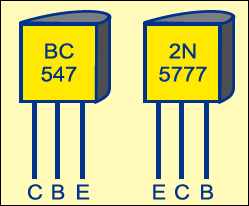
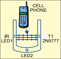
Pin configurations of BC547 and phototransistor 2N5777, and the proposed cell phone holder are shown in Figs 2 and 3, respectively.
The article was first published in July 2005 and has recently been updated.