


As families grow busier, maintaining medication schedules for seniors, home-bound patients, and children who may not fully understand medication routines can become increasingly difficult, especially when medicines must be taken at irregular intervals of two to four days.
This pillbox offers a low-cost, fully electronic, circuit-based solution, requiring minimal human intervention. The user only needs to fill the weekly dosage and ensure uninterrupted power supply.
POC Video Tutorial
The system provides medication reminders through both visual and audio alerts. As continuous audio signals may irritate patients, special care has been taken in the design. To prevent false triggering in the audio section (using the BT66/UM66 IC), optical isolation has been implemented through an optocoupler IC.

Each day, the reminder circuit activates a corresponding LED for about ten seconds to indicate the specific day of the week. In addition, an audio alert is generated for a preset duration (again, ten seconds in the present design) at every 24-hour interval.
After the ten-second alerts each day, the system resets itself to initiate the next 24-hour cycle. For demonstration purposes, the timing interval can be reduced to ten seconds (from 24 hours) and the alert duration to one second (from ten seconds), making it more convenient for video recording and testing.
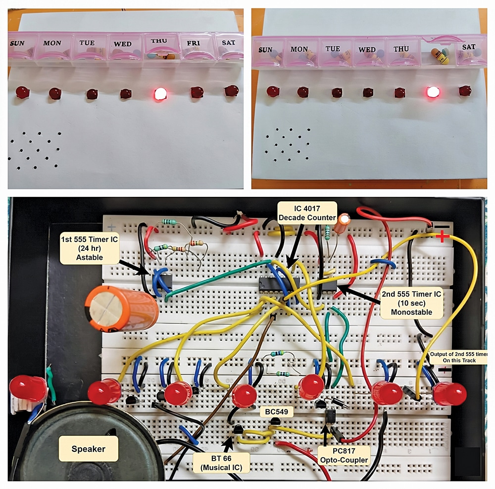
The proposed setup functions as a combined LED and buzzer alert system. Fig. 1 shows the author’s prototype of the complete setup, while Fig. 2 shows the system’s block diagram. To build this system, the required components are listed under Table 1 for the Bill of Materials.
| Table 1 Bill Of Materials | ||
| Components | Quantity | Purpose |
| 555 timer IC | 2 | One for astable (24 hours), one for monostable (10 sec) |
| CD4017 IC | 1 | For 7-day LED sequencing |
| BT66 music IC | 1 | Alert sound via the speaker |
| BC549 transistor | 8 | To switch the LEDs on/off and for the speaker |
| PC817 IC | 1 | To isolate BT66 from 555 IC |
| 5mm LEDs | 7 | One/day: Monday to Sunday |
| Resistor R1 (26.6MΩ) | 1 | For 24-hour time in 555 IC |
| Resistor R2 (1KΩ) | 1 | For 24-hour time in 555 IC |
| Resistor (1MΩ) | 1 | For 10-sec time in 2nd 555 IC |
| Capacitor (4700µf) | 1 | For 555 timing (24-hour) |
| Capacitor (9/10µf) | 1 | For 555 timing (10-sec) |
| Capacitor (0.0µf) | 2 | For noise removal |
| Speaker (8Ω, 0.5W) | 1 | For playing the sound |
| Breadboard | 2 | For prototyping the circuit |
| Jumper wires | – | For all connections |
| Power supply (5V) | 1 | Battery or DC adaptor |
| Diode 1N4007 | 1 | To protect IC PC817 |
| Table 2 Main Component Pin Connections | |||||||
| Connection | IC555A (24-hour Astable) | IC555B (10-second Monostable) | CD4017 | PC817 | BT66 | Speaker | BC549 |
| GND | Pin 1 | Pin 1 | Pin 8 | Pin 2 | – | Negative (–) | Emitter |
| +5V | Pin 8, Pin 4 | Pin 8, Pin 4 | Pin 16 | – | Pin 4 | Positive (+) | – |
| Control Voltage | Pin 50.01µF to GND | Pin 50.01µF to GND | – | – | – | – | – |
| Timing Network | Pins 2 and 64700µF to GND; Pin 7 26.6MΩ to +5V; 1kΩ between Pins 6 and 7 | Pins 6 and 71MΩ to +5V and 9µF to GND | – | – | – | – | – |
| Trigger/Input | – | Pin 2 | Pin 14 (clock from IC 555A Pin 3) | Pin 1 via 470Ω | Input from PC817 | – | Base |
| Output | Pin 3CD4017 Pin 14 and IC 555B Pin 2 | Pin 3PC817 and BC549 base | Q0-Q6 outputs | Pins 3 and 4 BT66 | Output BC549 base | Driven by BC549 | Collector Speaker |
| Reset/Enable | – | – | Pin 13GND, Pin 15Pin 6 (Q7 reset) | – | – | – | – |
| Other Pins | – | – | Pins 9, 11, 12 Not connected | – | – | – | – |
Circuit and working
Fig. 3 shows the circuit diagram of the pillbox with an adjustable reminder, designed to provide a daily audio alert in a sequential manner. It is built around two NE555 timers, a CD4017 decade counter, BC549 transistors, optocoupler PC817, a speaker, and a few other components.
