Experience the future of farm automation with our smart switch system. Simplify your operations, enhance productivity, and embrace a more streamlined approach to agricultural and industrial work. Say goodbye to manual constraints and embrace the power of innovation with our smart switch solution.
A smart switch system contains an Arduino board with GSM MODULE being remotely controlled by a smartphone. As technology is advancing, every sector getting smarter with the help of AI and IoT.
POC Video Tutorial In English
POC Video Tutorial In Hindi
Components Required
| s.no | Parts | Range | Quantity |
| 1 | Arduino Uno | 7-12 volt | 1 |
| 2 | Gsm with Gprs | 5 volt | 1 |
| 3 | Relay | 5 volt | Depends on machineries |
| 4 | DC-DC down converter | 2 volt to 35 Volt | 1 |
| 5 | Display (16*2) | 5 volt | 1 |
| 6 | Inter-Integrated Circuit(I2C) | 5 volt | 1 |
| 7 | contactors | 200v to 600v | Depends on machinery |
| 8 | Connecting wires | — | — |
| 9 | Solar panel | 50 w | 1 |
| 10 | Solar charge controller | 12v | 1 |
Why this Project?
As Modern houses are gradually shifting from conventional switches to centralized control systems, our idea mainly deals with the problem of farmers through the smart switch technology which is based on IoT and makes life easy, efficient, and better and enhances their standard of living so that they do not find difficulties in their daily day-to-day task thus making their daily routine efficient and productive. Involving remote-controlled switches.

Presently, conventional switches located in different parts of the farms make it difficult for the user to go near them to operate. Smart switches provide the most modern solution for smartphones. Our system majorly deals with when there is an assessment of the major agriculture and industrial works manually. this legacy of manual work sometimes constrains the worker to analyze the work by going in the field every time. Due to the uncertainty of power faults, the worker exhausts his energy by traveling a tractorable distance for the farm.
Our system deals with the eradication of this problem as our system consists of IoT-based technology powered by solar panels. this modern means of technology help in accessing the problem by sitting in one place. By means of this adaptive technology users can easily access the working condition and operative modes of machinery that are used in their farms by sitting at only one place instead of traveling long distances to the field in unfavorable conditions. The main objective is to provide facilities to the farmers.
You can also check the smart irrigation system project we build previously.
If you are looking for another DIY project, then you should check out our interesting Arduino projects otherwise continue reading…
Farm Automation System Circuit
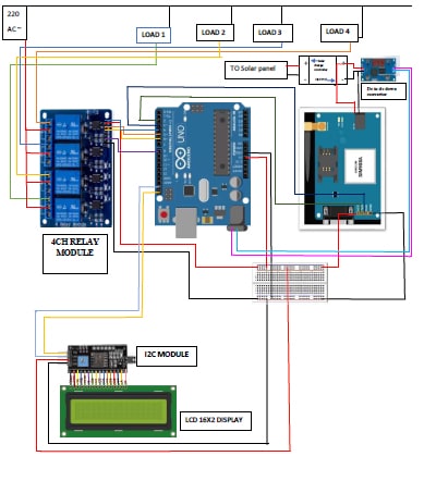
Working
Our smart switch system is made using Arduino UNO, GSM MODULE, and a smartphone. The aim of this system is to control different agricultural machinery using a smartphone.
When the power is turned on, the connection LED on the GSM MODULE starts blinking. We need to start the app (made through MIT APP INVENTER) on our smartphone and get connected to the GSM MODULE. If the pairing is successful, the LED becomes stable.
Now, in the app, we need to set different keys for different loads and their corresponding value that must be transmitted when that key is pressed. Then we are ready to control the loads.
When a key is pressed in the smartphone, the GSM MODULE receives the corresponding data and the intern transmits that data to Arduino. If we send “Motor on”, then the data received by the GSM MODULE. This data is transmitted to Arduino then compares the received data with the data written in the sketch and accordingly turns on the ‘Motor’.
A similar action can be applied to other keys and loads. Using this type of connection, we can control turn on or off different electrical machines using our Smartphones. also, we get the acknowledgment on our phones.

The GSM MODULE has 4 – pins: VCC, TX, RX, and GND. VCC and GND pins are connected to 5V and ground to Arduino UNO. The GSM MODULE works on 12V. The TX and RX pins of the GSM MODULE must be connected to the RX and TX pins of the Arduino.
When connecting RX to TX pins of Arduino (or any microcontroller as a matter of fact), we need to be careful as the pin can tolerate only 5V. But the voltage from the TX pin or Arduino will be 5V. So, a voltage divider network consisting of 10K and 20K resistors is used to reduce the voltage to 5V approximately.
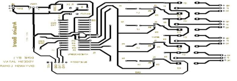
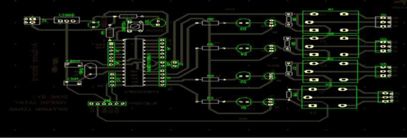
Farm Automation System – PCB Design
Arduino Code
#include <Wire.h>
#include <LiquidCrystal_I2C.h>
#include <SoftwareSerial.h>
LiquidCrystal_I2C Lcd(0x27,16,2); //set the lcd address to 0x27 for a 16 chars and 2 line
display
SoftwareSerial mySerial(3, 6);
String task;
void setup()
{
Lcd.init(); //initialize the lcd
Lcd.init();
Lcd.backlight(); // Turn on the backlight and print message.
mySerial.begin(9600); // Setting the baud rate of GSM Module.
Serial.begin(9600); // Setting the baud rate of Serial Monitor (Arduino).
pinMode(9,OUTPUT);
pinMode(10,OUTPUT);
pinMode(11,OUTPUT);
pinMode(12,OUTPUT);
digitalWrite(9,HIGH);
digitalWrite(10,HIGH);
digitalWrite(11,HIGH);
digitalWrite(12,HIGH);
delay(1000);
SendMessage();
Lcd.clear();
delay(500);
Lcd.print(" by Yogesh jatav");
delay(1000);
}
SMART SWITCH FOR AGRICULTURE IRRIGATION
void loop()
{
if (Serial.available()>0)
switch(Serial.read())
{
case 's':
SendMessage();
break;
case 'r':
RecieveMessage();
break;
}
if (mySerial.available()>0)
Serial.write(mySerial.read());
task=mySerial.readString();
if (task.indexOf("Switch1off")>=0){
Serial.println(task);
digitalWrite(9,HIGH);
Lcd.clear();
delay(500);
Lcd.print("Switch1off");
delay(5000);
Lcd.clear();
}
else if (task.indexOf("Switch1on")>=0){
Serial.println(task);
digitalWrite(9,LOW);
Lcd.clear();
SMART SWITCH FOR AGRICULTURE IRRIGATION
delay(500);
Lcd.print("Switch1on");
delay(5000);
Lcd.clear();
}
else if (task.indexOf("Switch2off")>=0){
Serial.println(task);
digitalWrite(10,HIGH);
Lcd.clear();
delay(500);
Lcd.print("Switch2OFF");
delay(5000);
Lcd.clear();
}
else if (task.indexOf("Switch2on")>=0){
Serial.println(task);
digitalWrite(10,LOW);
Lcd.clear();
delay(500);
Lcd.print("Switch2on");
delay(5000);
Lcd.clear();
}
else if (task.indexOf("Motoroff")>=0){
Serial.println(task);
digitalWrite(11,HIGH);
Lcd.clear();
delay(500);
Lcd.print("Motor OFF");
delay(5000);
SMART SWITCH FOR AGRICULTURE IRRIGATION
Lcd.clear();
}
else if (task.indexOf("Motoron")>=0){
Serial.println(task);
digitalWrite(11,LOW);
Lcd.clear();
delay(500);
Lcd.print("MOTOR ON");
delay(5000);
Lcd.clear();
}
else if (task.indexOf("Switch4off")>=0){
Serial.println(task);
digitalWrite(12,HIGH);
Lcd.clear();
delay(500);
Lcd.print("Switch4off");
delay(5000);
Lcd.clear();
}
else if (task.indexOf("Switch4on")>=0){
Serial.println(task);
digitalWrite(12,LOW);
Lcd.clear();
delay(500);
Lcd.print("Switch4on");
delay(5000);
Lcd.clear();
}
else if (task.indexOf("alloff")>=0){
SMART SWITCH FOR AGRICULTURE IRRIGATION
Serial.println(task);
digitalWrite(9,HIGH);
digitalWrite(10,HIGH);
digitalWrite(11,HIGH);
digitalWrite(12,HIGH);
Lcd.clear();
delay(500);
Lcd.print("ALL Switches OFF");
delay(5000);
Lcd.clear();
}
else if (task.indexOf("allon")>=0){
Serial.println(task);
digitalWrite(9,LOW);
digitalWrite(10,LOW);
digitalWrite(11,LOW);
digitalWrite(12,LOW);
Lcd.clear();
delay(500);
Lcd.print("ALL Switches ON");
delay(5000);
Lcd.clear();
}
}
void SendMessage()
{
mySerial.println("AT+CMGF=1"); //Sets the GSM Module in Text Mode
delay(1000); // Delay of 1000 milli seconds or 1 second
mySerial.println("AT+CMGS=\"+919872436823\"\r"); // Replace x with mobile number
SMART SWITCH FOR AGRICULTURE IRRIGATION
delay(1000);
mySerial.println("Home smart Switches on");// The SMS text you want to send
delay(1000);
mySerial.println((char)26);// ASCII code of CTRL+Z
delay(1000);
}
void RecieveMessage()
{
mySerial.println("AT+CNMI=2,2,0,0,0"); // AT Command to recieve a live SMS
delay(1000);
}
This is how you can make your own smart switch system for farm automation.