


 Technology is advancing daily and everything is turning smarter. A number of traditional devices that we use in our homes are becoming smarter now, including doorbells that are evolving with new features and styles. Today you will find many fancy doorbells in the market with touch switch system, but these are very costly to set up and everybody cannot afford them.
So, we have decided to help you make your own touch display doorbell. This multi-doorbell system has a lot of unique features, which will give you a new experience altogether. An interesting feature of this multi-doorbell system is that it has separate bells for each room in your home or office. It also has a special notification system to let visitors know whether the office is closed or not, or if any family member is available or not.
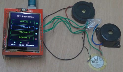
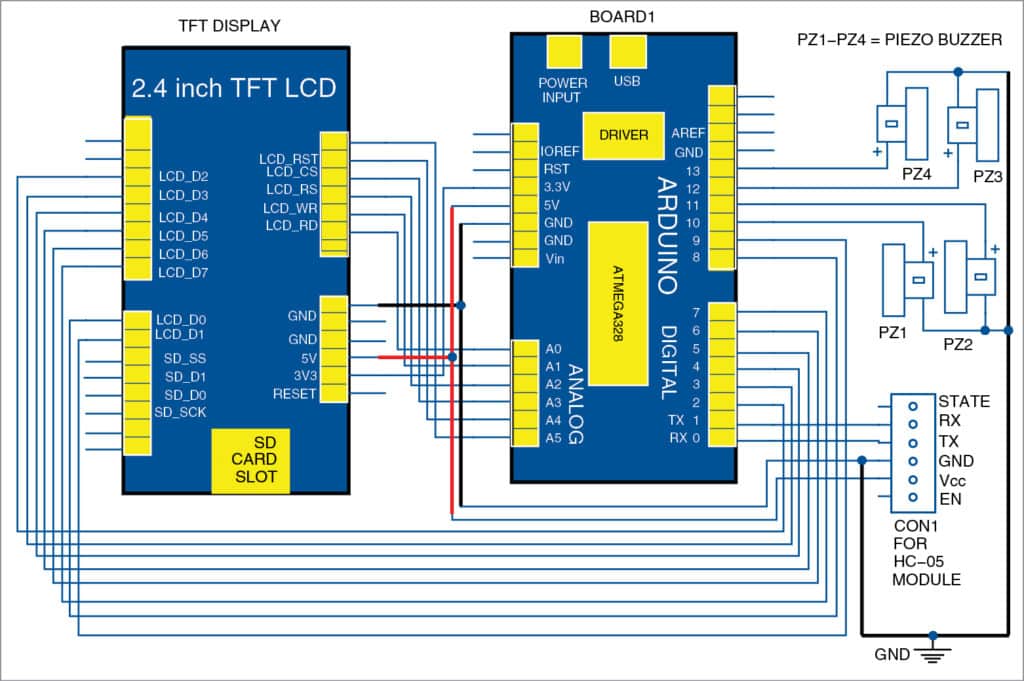
The circuit diagram of the smart touch-controlled multi-doorbell system is shown in Fig. 2. It consists of Arduino Uno, 6.1cm (2.4-inch) TFT display, Bluetooth HC-05 and four piezo buzzers.

Setting up Arduino library
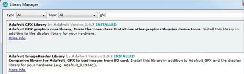
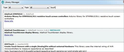
Install the required library in Arduino IDE. For this, go to Sketch menu and click on Manage Library. Search for library names—Adafruit GFX and TouchScreen—and click on Install.
Every touchscreen has its own library. Hence, find a library based on your TFT screen model, and install it. Here, we have used MCUFriend 2.4 TFT LCD library St7789v and installed it in Arduino IDE. Refer Figs 3, 4 and 5 for details.

Coding Arduino
Initialise the libraries in the code and declare the required variables (for example, home1, home2, home3 and home4) that you want to control for separate rooms or office cabins. Then, add fonts and colour codes for the TFT display to the following code:
#include <Fonts/FreeMonoBold24pt7b.h>
#include <Fonts/FreeMonoBold9pt7b.h>
#include <Fonts/FreeSerif12pt7b.h>
#include
///font
//home part
int home1=13;
int home2=12;
int home3=11;
int home4=10;
//home part
Next, create a function to get touch points. In this function, set the range of pressure to enable the touchscreen display to read the touch points. After that, map the values with the TFT display’s width and height to identify the touch points. The code to achieve these features is given below.
const int XP = 6, XM = A1, YP = A2, YM = 7;
//ID=0x9341
const int TS_LEFT=901,TS_RT=123,TS_
TOP=119,TS_BOT=881;
TouchScreen ts = TouchScreen(XP, YP, XM,
YM, 300);
Adafruit_GFX_Button on_btn, off_btn, on_
btn1, off_btn1;
int pixel_x, pixel_y; //Touch_getXY()
updates global vars
bool Touch_getXY(void)
{
TSPoint p = ts.getPoint();
pinMode(YP, OUTPUT); //restore shared pins
pinMode(XM, OUTPUT);
digitalWrite(YP, HIGH); //because TFT control pins
digitalWrite(XM, HIGH);
bool pressed = (p.z > MINPRESSURE && p.z
< MAXPRESSURE); if (pressed) { pixel_x = map(p.x, TS_LEFT, TS_RT, 0, tft.width()); //.kbv makes sense to me pixel_y = map(p.y, TS_TOP, TS_BOT, 0, tft.height()); } return pressed; }
Then, create a setup function to declare pin modes of Arduino and create buttons that you want to display on the screen of the touch display module.
In the code given below, we have created four buttons for four office rooms. We also created a few notification dots to show the working status of the bells. Colour of these notification dots will change according to status. For example, it will turn red when the office is closed, and green when it is open. The code to achieve these features is given below.
void setup(void) { Serial.begin(9600); pinMode(home1,OUTPUT); pinMode(home2,OUTPUT); pinMode(home3,OUTPUT); pinMode(home4,OUTPUT); uint16_t ID = tft.readID(); if (ID == 0xD3D3) ID = 0x9486; // write-only shield tft.begin(ID); tft.setRotation(0); //PORTRAIT tft.fillScreen(BLACK);//left.up.size. size tft.setFont(&FreeMonoBold9pt7b); on_btn.initButton(&tft, 105, 90, 190, 40, GREE, BLACK, GREE, “Office 1”, 1); off_btn.initButton( &tft, 105, 140, 190, 40, GREEN, BLACK, GREEN, “Office 2”, 1); on_btn1.initButton( &tft, 105, 190, 190, 40, GREE, BLACK, GREEN, “Office 3”, 1); off_btn1.initButton(&tft,105, 240, 190, 40, GREE, BLACK, GREEN, “Office 4”, 1); on_btn.drawButton(false); off_btn.drawButton(false); on_btn1.drawButton(false); off_btn1.drawButton(false);
Now, create a function to check and return the status of the buttons, that is, whether touch buttons are pressed or not. The code to achieve these features is given below.
Adafruit_GFX_Button *buttons[] = {&on_btn, &off_btn,&on_btn1, &off_btn1, NULL}; bool update_button(Adafruit_GFX_Button *b, bool down) { b->press(down && b->contains(pixel_x,
pixel_y));
if (b->justReleased())
b->drawButton(false);
if (b->justPressed())
b->drawButton(true);
return down;
}
bool update_button_list(Adafruit_GFX_
Button **pb)
{
bool down = Touch_getXY();
for (int i = 0 ; pb[i] != NULL; i++) {
update_button(pb[i], down);
}
return down;
}
In loop function, create several ‘if conditions’ that will check the status of the buttons and perform the tasks according to code.
Testing
After connecting the components, crosscheck the wirings and circuit connections. If all connections are alright, power on Arduino board with 5V DC to 12V DC—you can also use an AC-to-DC adaptor such as a cellphone charger or any 9V battery.
This touch-controlled multi-doorbell should be installed at the main gate of the building. Then extend the wires of doorbell speaker to the respective room or office cabin.
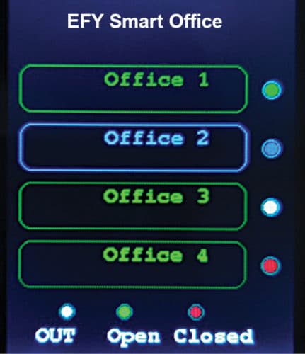
When you power on Arduino, you will get a menu with names of people in the rooms on the TFT screen. By default, the buttons and status on the screen will be blue. If you touch the button, say, office 1, it will become green and the doorbell will ring. Touch the name/office where you want to ring the bell. If you want to change the status, like office is closed or occupant is out of office, you can do it using Bluetooth module (HC-05). Simply connect the circuit to a suitable Bluetooth app on your smartphone through HC-05 module.
Once Bluetooth on the smartphone and HC-05 are connected, send commands set previously in the code to change status. Screenshot of the notification when the person is out of office room 3, the status dot will turn white, as shown in Fig. 6. Bluetooth app is easily available on Google Play Store.
Note that, each piezo buzzer can be replaced with an actual doorbell along with a suitable driver circuit.
For downloading source code; Click here
You can also check the touchless Arduino doorbell that we build to protect from the corona.
Ashwini Kumar Sinha is an electronics hobbyist and tech journalist at EFYi
This article was first published online on electronicsforu.com. You can read the full draft of the article here.
Please recoment more aurdino projects
YOu can check out Arduino projects lists here: https://www.electronicsforu.com/?s=arduino