


In a previous project, we developed a smartwatch with Wi-Fi analysis and health monitoring capabilities featuring an ESP32 Dev board. Building upon this concept, we are now introducing a new iteration: a smartwatch with Keyboard and Mouse functionalities designed to function as a wearable and portable Human Interface Device (HID). With this enhancement, users can utilize the watch as both a keyboard and mouse, allowing them to control their phones and laptops directly from their wrists.
POC Video Tutorial In English
POC Video Tutorial In Hindi
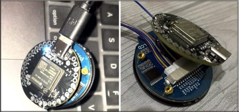
This innovative device effectively transforms into a portable keyboard and mouse, offering unparalleled convenience and versatility. In our previous design, we encountered size limitations with the ESP32 Dev board, which made it unsuitable for integration into a smartwatch. To address this issue, we have replaced the board with the INDUSBOARD COIN, a compact solution perfectly sized for our display.
Our smartwatch features a GC9A01 Driver and CST816S Capacitive Touch Driver-based display, seamlessly connected to the Indusbaord via SPI and I2C pins on the board. This setup ensures efficient communication and integration, allowing for smooth operation and optimal user experience. With these advancements, our smartwatch promises to deliver enhanced functionality and usability, bringing the concept of a wearable keyboard and mouse to fruition.

First, you need to collect the following components
Bill of Materials
| Components | Description | Quantity | Price |
| IndusBaord | Dev Boord | 1 | 1500 |
| USB Type C | Adapter | 1 | 100 |
| Round Touch Display | GC9A01 Driver And CST816S Capacitive Touch Driver | 1 | 1000 |
Smartwatch with Keyboard and Mouse – Code
The code is developed using Arduino and the TFT-espi library along with the CST816S touch driver library to drive the display and touchscreen functionalities. Fortunately, the HID library comes pre-installed with the ESP32s2 Board SDK, simplifying the setup process. All required is to install the TFT-espi and CST816 libraries, which can be found in the Arduino Library Manager.
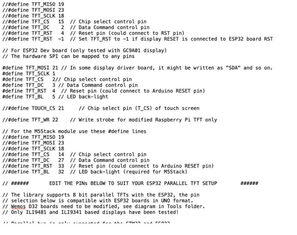
Next, we need to configure the display driver and SPI pins in the library to ensure compatibility with the Indusboard. Any available pins can be used for SPI, but for our setup, we’ve chosen pins 21, 1, 2, 3, and 4. Additionally, pins 5 and 6 are designated for I2C communication with the touch display.
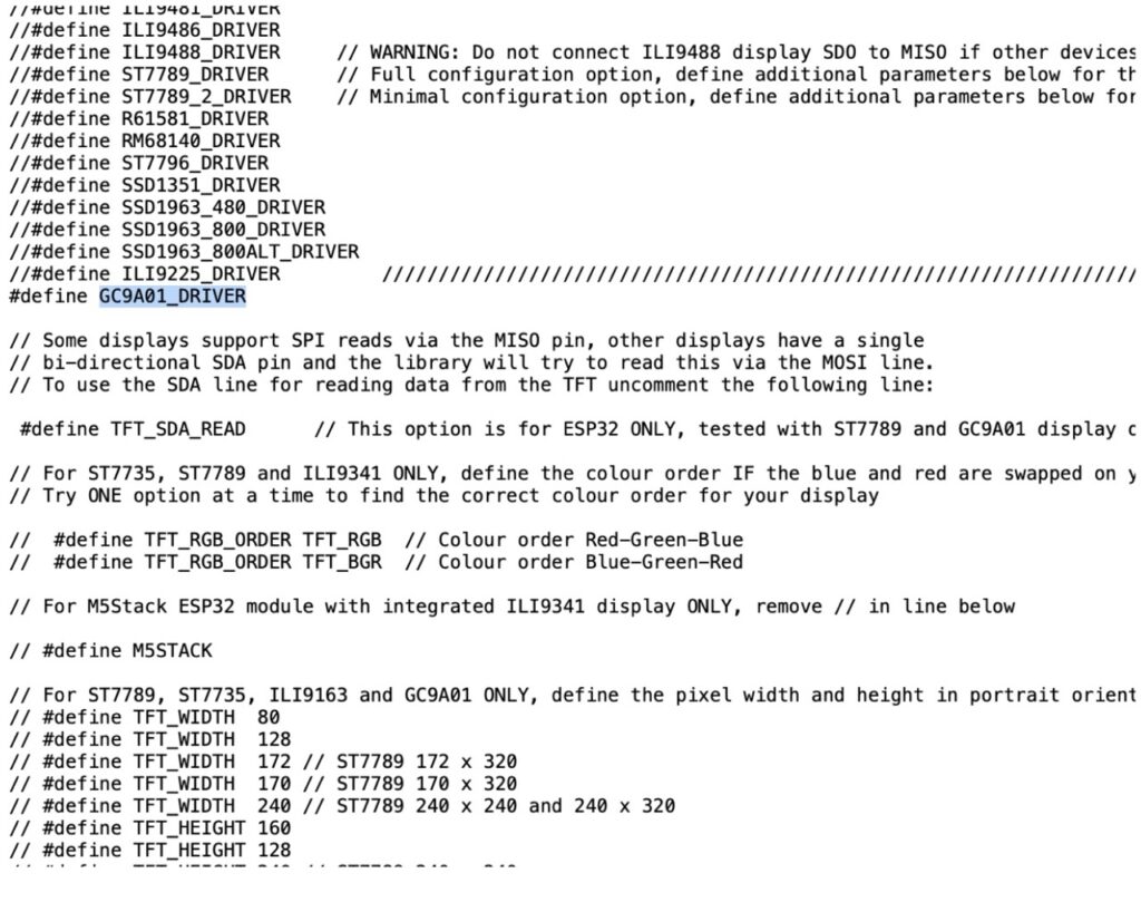
To configure the SPI and display settings, navigate to the TFT-espi library folder located in the Arduino Library directory. Open the user configuration file within the library and uncomment the GC9A01_Driver. Then, proceed to set the MISO, MOSI, CS, and DC pins in the configuration file according to your setup.
For detailed instructions and visuals, please refer to Figures 2 and 3 for a step-by-step guide. These steps ensure seamless integration of the display and touch functionalities with the Indusboard, enabling the smooth operation of the smartwatch project.
Now we make two codes, one for the keyboard and the other for the Trackpad touch mouse.
Code For TouchPad Mouse
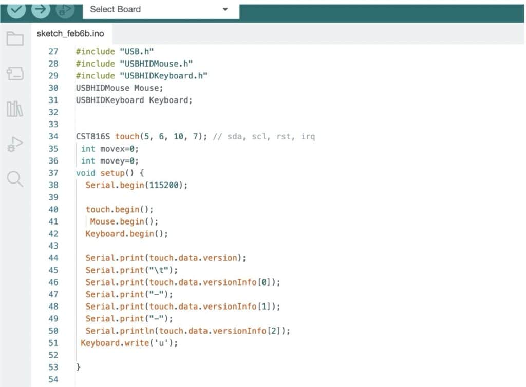
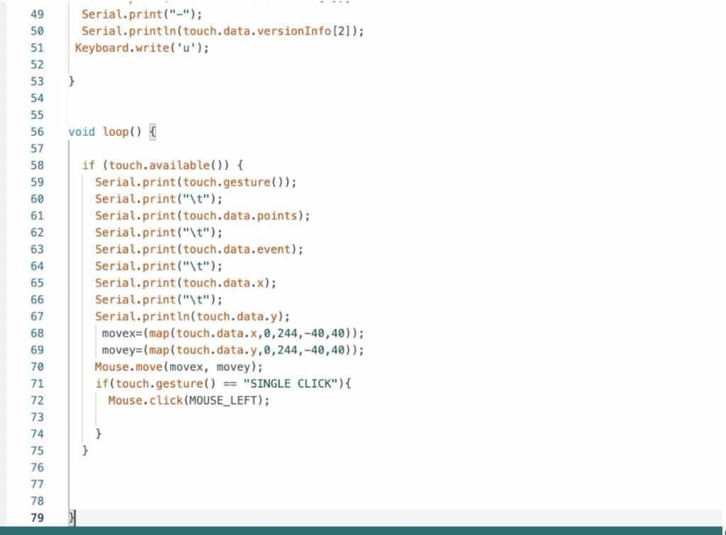
We begin by including the mouse HID library in our Arduino sketch to implement mouse functionality. Then, we define the I2C pins for the display. On the INDUS board, any pin can serve as an I2C pin, so we’ve selected pins 5 and 6 for SDA and SCL, respectively.
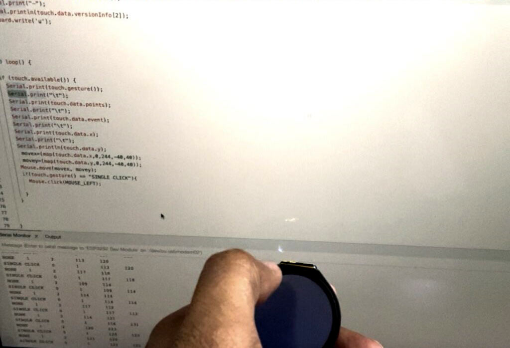
In the code, we monitor the touch points on the display and map them to mouse movements. Additionally, we utilize gestures such as left swipe, right swipe, single tap, and double tap to simulate mouse actions such as left click, right click, and scroll.
Here’s a summary of the steps involved:
- Include the mouse HID library in the Arduino sketch.
- Define the I2C pins for the display. (For example, use pins 5 and 6 as SDA and SCL.)
- Monitor touch points on the display and map them to mouse movements.
- Implement gestures such as left swipe, right swipe, single tap, and double tap to trigger mouse actions like left-click, right-click, and scroll.
By following these steps, we can seamlessly integrate mouse functionality into our smartwatch project, enhancing its usability and versatility.
Code for Keybaord
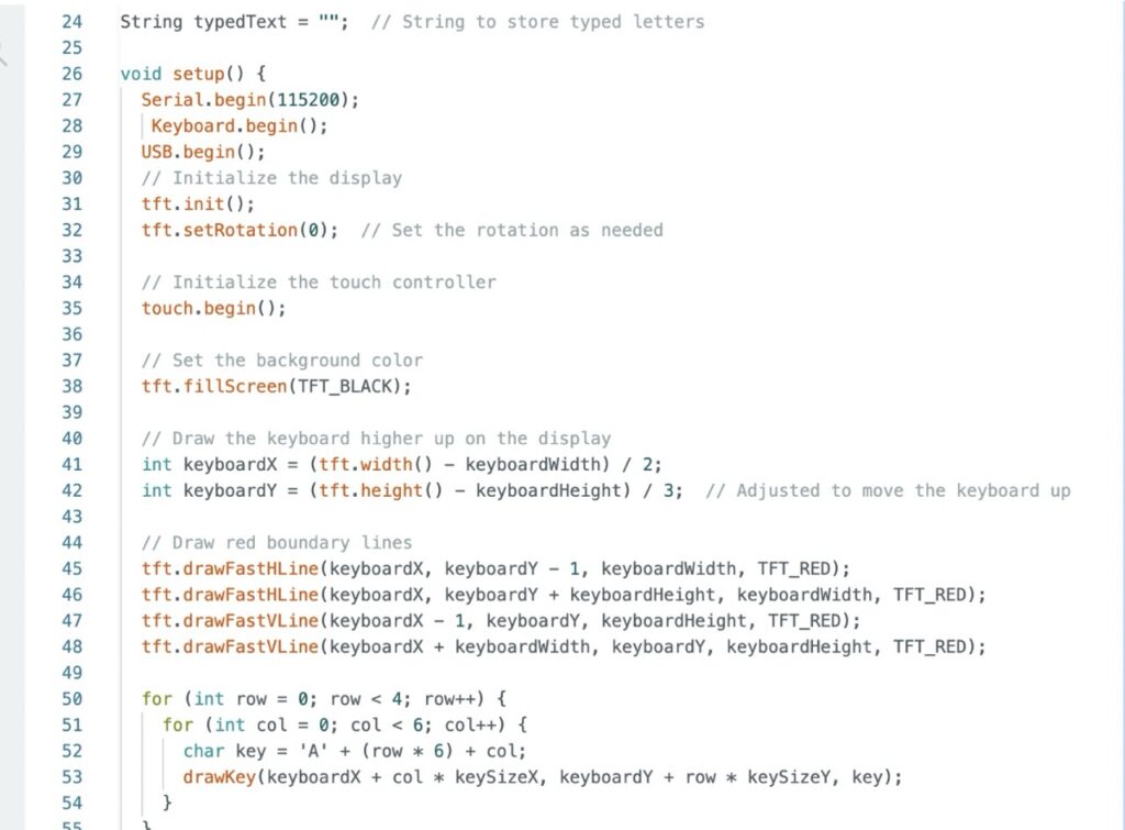
To start, we include the HID library for the Indusboard in our Arduino sketch. Then, we set the I2C pins for the touch display driver. Since any pins on the Indusboard can be configured as I2C pins, we’ll use pins 5 and 6 for this purpose.
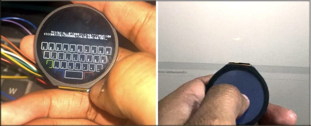
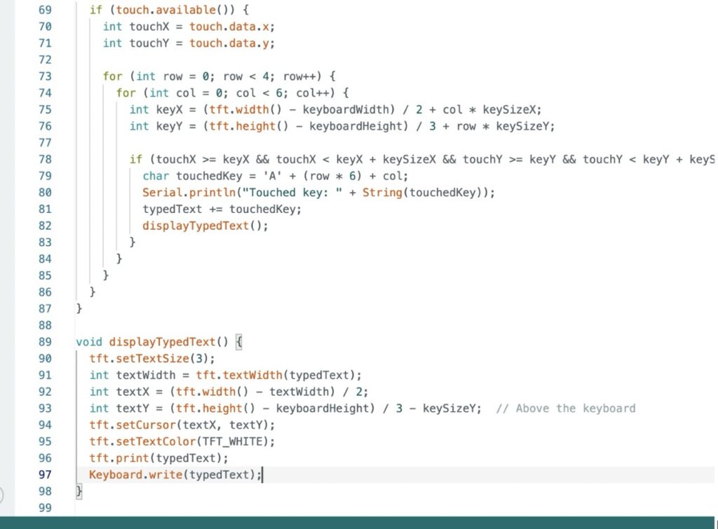
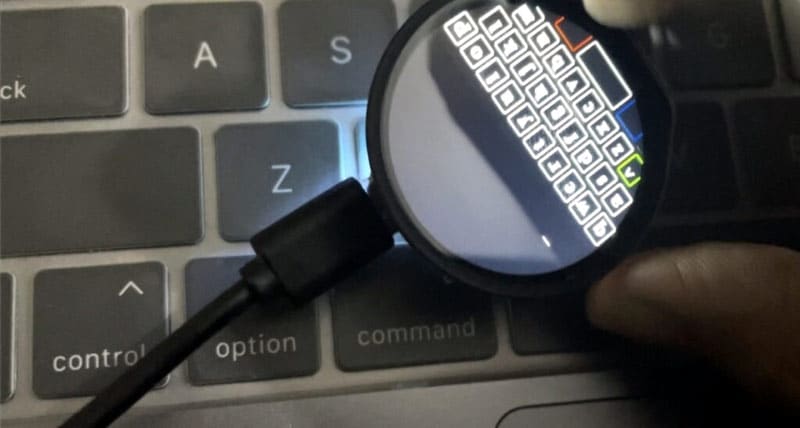
Next, we create the keyboard layout and display it on the touchscreen. This layout allows users to see the keys they’re pressing. We then map the touchpoints on the display to the corresponding keys on the keyboard layout to detect which key the user has touched. Once a key is touched, we register that input and send it as HID input to the connected laptop.
For detailed instructions and visuals, please refer to Figures 6 and 7 for a step-by-step guide on implementing this process. By following these steps, we can seamlessly integrate keyboard functionality into our smartwatch project, allowing users to type directly from their wrist.
Now upload the code by selecting the ESP32S2 as the chip and the right port.
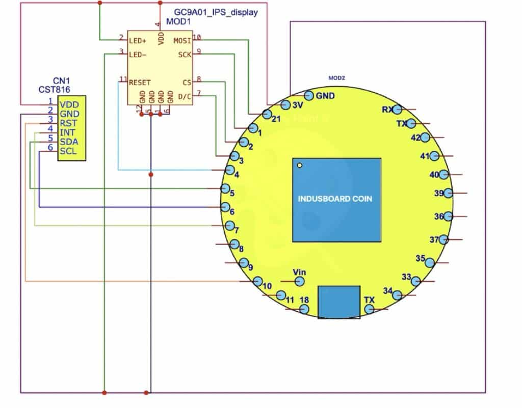
Circuit Diagram
To connect the display and touch pins according to the circuit diagram, follow these steps:
- Refer to Figure 8 for the circuit diagram, which illustrates how to connect the display and touch pins.
- Solder the pins behind the Indusboard according to the diagram.
- Ensure that the Indusboard fits perfectly behind the display, resembling the size and shape of a watch.
- Refer to Figure 9 for a visual guide on soldering and placing the Indusboard.
By following these instructions and referring to the provided diagrams, you can successfully connect the display and touch pins and secure the Indusboard behind the display, creating a compact and functional smartwatch prototype.
Testing
Once the Indusboard is powered, you’ll notice that upon uploading the keyboard code, the keyboard layout will appear on the display. When you touch any key on the keyboard layout, the corresponding message will be typed.
Similarly, when you upload the mouse code and move your finger on the display screen, the mouse pointer (cursor) will move along with your touch movements.
To further enhance functionality, you can combine both the keyboard and mouse code into a single program. This combined code will allow for seamless switching between keyboard and mouse functionalities, providing users with a more intuitive and versatile experience.
By integrating both keyboard and mouse functionalities into a single codebase, you can create a smartwatch prototype that offers comprehensive input capabilities, making it a powerful tool for various applications and tasks.
Other IndusBoard-based Projects
- Touch Switch Board
- IndusBoard OTA Programming
- Interfacing OLED Display with IndusBoard
- Smallest Pulse Oximeter
- RFID Hacking Cloning RFID Tags


Dear Sirs,
please can you post the link for the codes of this project?
Kind Regards
Mitsos
Added at the bottom of article