


This solar powered pedestal lighting system uses power LEDs for lighting. Solar energy is first converted into DC electricity by a solar photovoltaic cell and used to charge a storage battery. The solar energy stored in the battery is utilised at night for pedestal lighting using power LEDs.
Connection of power LEDs on the pedestal is through a control unit that has a logic circuit for switch-’on’ at night and switch-’off’ in daytime. The solar panel to charge the storage battery is selected based on the lighting load and duration for which it is required to be ‘on.’
Solar Powered Pedestal Lighting System Block Diagram
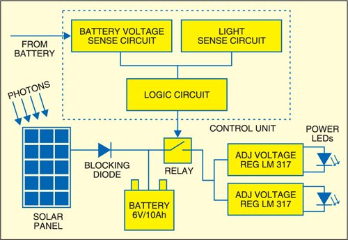
Fig. 1 shows the block diagram of the solar-powered pedestal lighting system using power LEDs. The specifications of the solar panel used here are:

- Maximum power: 10.0W
- Voltage at max. power: 17.0V
- Current max. power: 0.6A
- Short-circuit current: 0.7A
- Open-circuit voltage: 21.8V
Circuit connections
The solar panel output is connected to the battery through a blocking diode (D1). Diode D1 protects the panel from reverse power flow. During daytime, sunlight is directly converted into DC electricity by solar cells, hence the power flow is from the solar panel to the storage battery. At night, there is no sunlight and hence the solar panel is not generating the power and there may be reverse current flow, i.e., from the battery to the solar panel. Diode D1 (1N5408) prevents flow of current into the solar panel from the battery and thus protects it from damage.
The battery rating used here is 6V, 4.5Ah and the type is lead-acid. The solar panel output is directly connected through a switch to the battery for charging.
The control unit used in the pedestal lighting system consists of the battery-voltage-sensing circuit, light-sensing circuit and logic circuit.
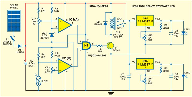
The battery-voltage-sensing circuit protects the battery from over-discharge. The battery voltage level is set by the potential divider arrangement. The potential divider voltage is compared with reference voltage by comparator circuit built around op-amp IC LM358 (IC1). The reference voltage at pin 2 of IC1 (A) is fixed by zener diode ZD1. The comparator output will go low when the battery voltage goes below the set voltage. The battery cut-off range is controlled by adjusting potmeter VR1. The output of op-amp IC1 (A) is fed to the logic circuit.
Circuit operation
The light-sensing circuit is used to turn on the power LED circuit at night and turn off in daytime. Light is sensed by light-dependent resistor LDR1. Depending on the light intensity, the resistance value of LDR1 varies. When the light intensity is high it offers low resistance and when the light intensity is low the resistance is high. LDR1 is connected in the potential divider circuit.
LDR1-controlled output at pin 5 of IC1 is compared with reference voltage. The reference voltage is created by the potential divider at pin 6 of IC1 (B) and controlled by adjusting potmeter VR2. The output of IC1 (B) is fed to the logic circuit built around AND gate N1 of IC2. The outputs of the battery-voltage-sensing circuit and light-sensing circuit are fed to the logic circuit (two-input quad AND gate 74LS08).
When both the inputs of the AND gate are high, its output is also high. The high output of the AND gate at its pin 3 is fed to relay-driver transistor T1 for driving the relay, which controls the power supply to the LED circuit.
Energisation of relay RL1 enables the power-LED-driver circuit built around IC3 and IC4. The power-LED-driver is basically an adjustable voltage regulator circuit (LM317) that is capable of driving up to 3W loads.
Component ratings
The power LED rating is 3W. It has a negative temperature coefficient, so when temperature increases current rises beyond the rated value. This can be controlled by providing a heat-sink and the voltage applied to the LED. The output of the voltage regulator can be adjusted by varying potmeters VR3 and VR4 in the regulator. Thus the voltage applied to the LED may vary between 3.0V and 3.4V. The charging current for the battery should be 10 per cent of its ampere-hour rating. In the circuit given here, the battery rating is 6V, 4.5Ah, and to meet the required charging current, a 10W solar panel has been selected.
Check our other solar electronics projects you can build at home.
The article was first published in April 2007 and has recently been updated.

Would like to purchase Solar Powered Pedestal Lighting System” Complete Kit. Kindly send me the price and other relevant details.
Thanks.
I need the names of the all elements of fig 2 circuit ? please tell me