 When soldering, sometimes the need arises to control the temperature of the soldering iron. It is not possible to change the solder iron every time. If you’re just soldering small resistors and ICs, 15 Watts will probably suffice, but you may have to wait a bit in between joints for the tip to recover. If you’re soldering larger components, especially ones with heat sinks (like voltage regulators), or doing a lot of soldering, you’ll probably want a 25 or 30 Watt iron.
For soldering larger things like 10 gauge copper wire, motor casings, or large heat sinks, you may need upwards of a 50 Watt iron or more. Soldering irons are available in different wattage and usually run at 230V AC mains. However, these have no temperature control. Low-voltage soldering irons (e.g. 12V) generally form part of a soldering station and are designed to be used with a temperature controller. A proper temperature controlled soldering iron or station is expensive. Here is a simple circuit that provides manual control of the temperature of an ordinary 12V AC soldering iron.
Soldering iron temperature controller circuit
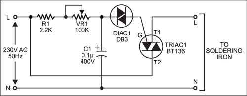
Here is a simple soldering iron temperature controller circuit to control the temperature of a soldering iron. It is especially useful if the soldering iron is to be kept on for long since you can control the heat dissipation from the iron. When a soldering iron is switched on, the iron takes time to reach the solder’s melting point. Simply connect this circuit to the soldering iron as shown in the figure and the iron reaches the solder’s melting point quickly.
The circuit consists of TRIAC1, DIAC1, potentiometer VR1, a resistor & a capacitor. Triacs are widely used in AC power control applications. They are able to switch high voltages and high levels of current, and over both parts of an AC waveform. This makes triac circuits ideal for use in a variety of applications where power switching is needed. One particular use of triac circuits is in light dimmers for domestic lighting, and they are also used in many other power control situations including motor control.
A diac is a full-wave or bi-directional semiconductor switch that can be turned on in both forward and reverse polarities. The name diac comes from the words Diode AC switch. The diac is an electronics component that is widely used to assist even triggering of a triac when used in AC switches and as a result they are often found in light dimmers such as those used in domestic lighting. A typical diac-triac circuit is used for smooth control of ac power to a heater.

Triac BT136 is fired at different phase angles to get temperatures varying from zero to maximum. A diac is used to control the triac firing in both directions. Potentiometer VR1 is used for setting the temperature of the soldering iron.
The circuit can be housed in a box with the potentiometer fixed on the side such that its knob can be used from outside the box to adjust the soldering iron’s temperature.
The article was first published in November 2004 and has recently been updated.


I have built this circuit . It is working fine without load but when i connected a load then no voltage regulation at output. Without load voltage can be varied from 40v to 200v, but on load variation range is 180v to 200v. that is the problem i have faced
Hello firstly I have to admit I am a novice at electronics but I do follow the schematics very carefully.
So having assembled the circuit for the soldering iron temperature control module, I was very surprised when
the Triac was destroyed the instant the power was switched on. After checking and re-assembling the circuit with a new BD136 I was disappointed with the same result. It seems there should be some protection between the 2.2k resister and the T2 terminal of the Triac.
I would be grateful for any advice to remedy this fault before I destroy any more components.
Thank you for your feedback. We will review the circuit with our Team.
To save your components !
You can just buy a fan regulator which has same design and probably it can switch high load such as motor of fan so soldering iron can easily be driven by it.
How to connect externally or internally led dispaly for temp indication in soldering iron