


 If you are looking for a compact and inexpensive add-on audio amplifier for your digital surround sound system or computer, then this subwoofer amplifier circuit is suitable for your needs. It delivers 15W per channel in stereo mode and about 29W in bridge mono mode from a box as small as a house brick.
Many low-cost DVD players availabe in the market do not have in-builtaudio amplifiers. To enjoy stereophonic sound, you have to buy separate left and right speakers. Moreover, to play a DVD in Dolby Digital format, you would probably need five amplifiers and speakers, one for each of the channels.
Like many audio projects published earlier in EFY, subwoofer amplifier circuit can upgrade an audio system according to your personal taste. It helps a low-cost DVD player to play excellent Dolby Digital (AC-3) surround sound.

Dolby Digital ‘5.1 channel’ systems have separate channel outputs, with the centre–front signal quite different from the front, left and right ones. Many DVDs have main screen dialogues on the centre-front track, so to hear dialogues, you need a centre front amplifier and speaker. Besides, there are separate rear channel signals with Dolby Digital for MPEG and DTS encoding, and to hear them you need two separate amplifiers and speakers. The subwoofer track (low frequency effect, LFE) is quite discrete in Dolby Digital encoding. It delivers most of the grunt for explosions. So, if you watch an action movie without a subwoofer, you miss out most of the sound effects.
In brief, in order to enjoy Dolby Digital format movies, one needs three extra speakers and matching amplifiers apart from stereo system. Getting extra speakers at affordable price is not a problem, but it is not the case with add-on amplifier for a stereo or bridged mono system.
The circuit described in the article provides two 15W RMS power amplifier channels, with low distortion noise and a good frequency response. The input sensitivity is good, too. You need around 200mV input to produce full output, suitable for use with ‘line’ output on DVD players with in-built Dolby Digital decoders.
In fact, one or two brick amplifiers can be used with the DVD player to get an effective output from your surround sound system. This amplifier is also suitable for enhancing multimedia in a computer, allowing you to play external speakers.
Subwoofer amplifier circuit
The subwoofer amplifier circuit is simple. It consists of power supply and audio power amplifier sections. The simple scheme of the two channels to be driven from one of the inputs facilitates a hassle-free bridge mono mode operation.
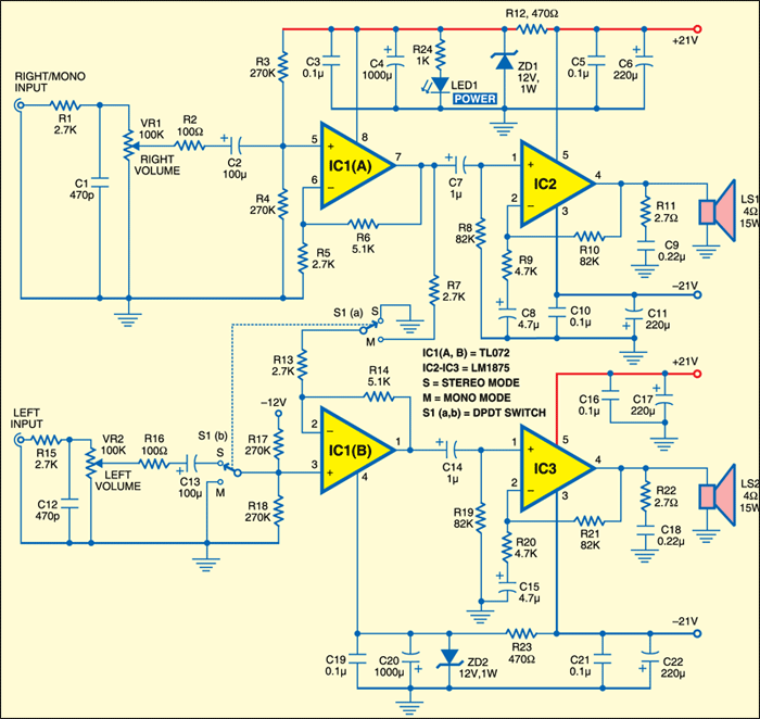
This subwoofer amplifier circuit consists of a TL072 low-noise JFET dual operational amplifier (IC1) and two LM1875 (IC2 and IC3) power amplifiers.
Circuit operation
In stereo mode, each half of the TL072 operates as a non-inverting input amplifier, with a gain of about 2.8 times as determined by feedback resistors R5 and R6. In front of each input amplifier there is a low-pass filter for RF suppression (R1/C1 and R15/C12), followed by volume controls VR1 and VR2 and blocking capacitors C2 and C13.
Switch S1 is used to select bridge mono mode operation. When it is switched to mono position ‘M‘, the non-inverting input of IC1(B) is connected to the ground, making the left input of the brick ineffective. However, at inverting terminal of IC1(B), the cold end of resistor R13 is disconnected from the ground and connected to R7. It is now converted into a unity gain inverting stage and the output of IC1(A) is connected to IC1(B) through R7. This converts the front end to produce dual phase drive signals from the right channel input. In stereo mode, each of the amplifier stage drives the right and the left speaker connected across pin 4 of IC2 and IC3, respectively.
Each input stage drives one of the LM1875 power stages (IC2 and IC3) with traditional circuitry. Coupling capacitors C7 and C14 provide DC blocking, with the power stage voltage gains set to around 18 by feedback networks R9/R10 and R20/R21. Resistors R8 and R19 provide biasing for the non-inverting inputs, while C8/C15 provide AC grounding for the feedback networks.
R11 and C9, and R22 and C18, are Zobel impedance stabilising circuits used across power amplifier output to ensure maximum AC stability.
Output stages operate from DC rails of ±21V, which are provided from the power supply, using 21V-0-21V, 2A centre-tapped transformer.
Power supply circuit
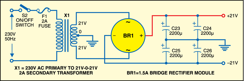
The transformer drives the bridge rectifier module BR1 and four 2200μF capacitors to provide +21V and –21V DC supplies. The left and the right channel input stages formed by the TL072 op-amp require ±12V DC supplies for the operation. While +12V is obtained from resistor R12 and zener diode ZD1, –12V is obtained from resistor R23 and zener diode ZD2.
Construction
Construction steps involve PCB design, mounting of components on the PCB, cabinet design, connecting the power supply to PCB and extending wires from the PCB to the front and rear panels.
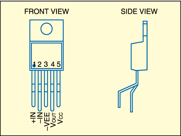
Having conventional circuitry, the amplifier has to be squeezed into a low-cost brick shaped box. 21V-0-21V/2A power transformer occupies almost half of the internal space. To make room for the PCB of amplifier circuit in the brick cabinet, part of power supply section is mounted on a separate PCB so that it can be fixed on the rear side of the cabinet. Pin details of IC LM1875 are shown in above. Note that proper finned heatsinks should be used for power amplifier ICs (LM1875). While designing PCB layout, there is need to determine a proper location on the board to mount the heat sinks for IC2 and IC3.
A single-side PCB and its component layout can be downloaded from the link below. The PCB for the power supply section can be separated from the amplifier section by cutting along the straight line shown in the attachments.
Download PCB and component layout PDFs: click here
The construction steps should be followed in the following sequence: Mount the PCB terminals and connectors, followed by low-profile components (resistors and zeners), then smaller capacitors such as ceramics, and finally larger electrolytic capacitors. Ensure correct placement of zener diodes in the PCB as per schematic diagrams. In fact, you may like to fit a good-quality 8-pin DIL socket to the board to allow the amplifier IC1 to be conveniently plugged in later on.
The PCB can fit inside the box by proper drilling, reaming and cutting holes on the front and rear panels and the base of the cabinet.
Note that besides mounting holes in the rear panel for the speaker terminal, there should be clearance holes for other terminals also. On the front panel, the holes for volume control, mono/stereo switch and RCA input sockets are all circular, so they can be drilled and reamed. The holes for RCA sockets should be large enough to accept plastic insulating sleeves. Two holes have to be drilled for volume controls on the front panel.
Larger holes for the mains fuse holder (F1) and power switch (S2) are irregular. So, if you prepare them by hand, careful drilling is required besides a nibbling tool and/or small jeweller‘s files.
Once the wires are connected, carefully place the PCB inside the cabinet. Use the insulation sleeves, flat washers, lock washers and nuts, so that everything is in place before screws are tightened. Mount volume control knobs into their respective holes on the front panel. (You may need to slip a couple of thin washers into the spindles of the knobs, to prevent them from protruding inside the cabinet.) With the PCB fitted at the bottom of the cabinet, bring speaker
wires from connecting points, marked as LS1 and LS2, respectively, on the PCB, to the rear panel.
Fit four screws along with suitable spacers into the holes located in four corners of the cabinet bottom to tighten up the PCB firmly in its place. You can place the power transformer inside the cabinet and tighten it to the cabinet bottom with nuts and bolts.
Now take a pair of tweezers or needle nose pliers and carefully push the tip of each wire through holes for left and right RCA input sockets and stereo/mono switch, respectively. Fix the sockets and switch firmly to the cabinet by tightening the respective nuts. Make sure that the wires are not twisted together or unduly strained. Also, make sure that sufficient length of wires from the PCB to the cabinet are provided for speakers, switches, volume controls and power supply. Following these steps, solder each wire to the PCB pad and clip off any excess parts. This essentially completes the wiring.
Testing subwoofer amplifier circuit
As there are no adjustments to be made, connect the amplifier to a pair of speakers, source of power and provide mono or stereo signals, before listening to the sound.
It is a good idea to perform a functional check of the power supply before IC TL072 (IC1) is inserted into its socket on the PCB. So, turn on the power, then measure the voltages across the supply, which should give +21V and –21V outputs, respectively. Now try checking the voltages at pins 8 and 4 of the socket for IC1, which should be +12V and –12V, respectively. If all the four voltages fulfill the measurement criteria, then turn off the power, unplug the mains cord, insert IC1 in the socket and fit the top of the cabinet.
If you are concerned about the proximity of the sleeved transformer’s primary connections to the side of the cabinet, you may attach a protective inverted-L cover of ‘elephant hide’ or a similar fireproof insulating sheet over the side facing the transformer.
The amplifier is now ready for use.
The project was published in December 2009 and has recently been updated.
Can i use a 3.5 mm audio output as the input to this subwoofer amp?
Comment: the 21-0-21 v transformer used in the circuit will give 21×1.41 = 29.61 volts which is equal to 59.22 volts in total to be fed to lm1875 ic which is the maximum supply volt of the ic. But not all ic available in market can sustain such high voltage as some ics may be chinese ones. So please suggest safe working voltage
Comment: where can I get the 21-0-21 v, 2A transformer ?