


UV rays are reputed to have versatile characteristics in various capacities. In the era of mobile screens, and the increasing popularity of smartwatches, many of us look at our smartwatches first thing in the morning. But are they safe? Do they emit UV rays that could harm our eyes?
Here we designed the UV Radiation Testing Device using Arduino.
The proposed setup is used to measure the intensity of ultraviolet (UV) rays generated by a UV-C lamp, which is generally meant for sanitization purposes. Also, we have investigated the emission of UV rays by smartwatches to reveal their intensity and harmfulness. Fig. 1 shows the author’s prototype used for various experiments.

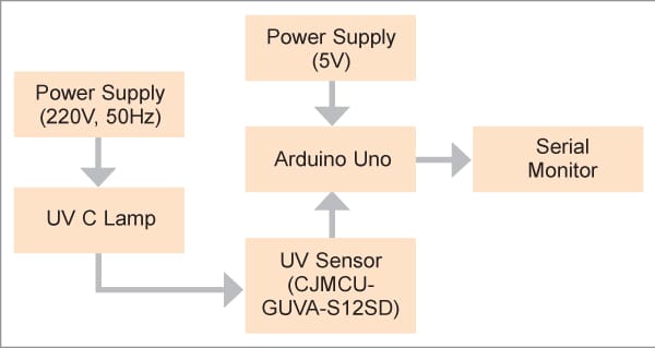
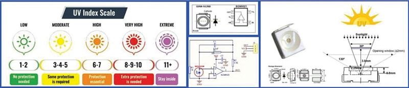
It demonstrates the responsivity across various wavelengths and the variation in output voltage with respect to the UV index. Fig. 2 is the block diagram representation of the entire setup.
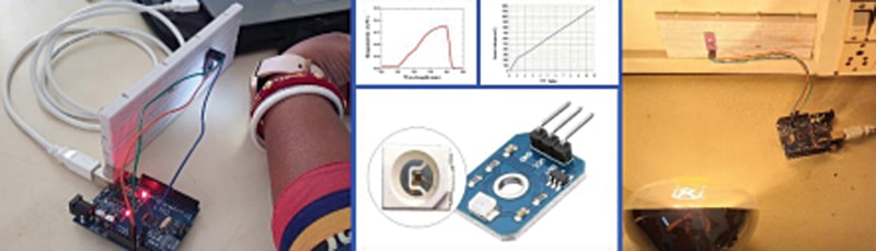
The GUVA-S12SD UV sensor chip is suitable for detecting UV radiation from any light source, including sunlight, fire, torches, lamps, LEDs, and heat lamps. It can be easily integrated into any application where you want to monitor the amount of UV light and it is simple to connect to any microcontroller.
It is an analog UV light-to-voltage converter for measuring the intensity of UV light. This true UV detector detects light only from 240nm to 370nm, which is the UV-B and most of the UV-A spectrum. It also picks up the upper end of the UV-C spectrum.
The UV index is an important vehicle to raise public awareness of the risks of excessive exposure to UV radiation, and to alert people about the need to adopt protective measures.
As part of an international effort, the UV index was developed by the World Health Organization (WHO), the United Nations Environment Programme, the World Meteorological Organisation, and the International Commission on Non-Ionizing Radiation Protection. Fig. 3 represents the widely accepted UV index chart.
As evident from Fig. 3, the smaller indices represent lesser intensity. The higher intensities are meant for variable tasks like industrial processes, medical and dental practices, bacteria sanitization, creating fluorescent effects, curing inks and resins, phototherapy, and sun tanning.
The purpose varies with respect to the wavelengths and the intensities. UV lamps emit radiation that is enough to kill germs. They are used in healthcare to sterilize surgical instruments. UV rays are also used in the purification of water and the pharmaceutical industry.
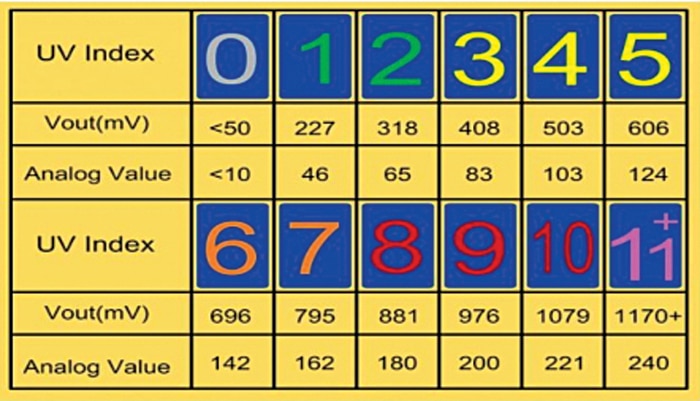
Fig. 3 shows the UV index, the output voltage (in mV), and the corresponding analog value. GUVA-S12SD is a gallium nitride material-based Schottky-type photodiode, optimized for photovoltaic mode operation. It is followed by an op-amp IC SGM8521. It is a rail-to-rail input and output voltage feedback amplifier.
Op-amps that use the complete span between negative and positive supply voltages are called rail-to-rail op-amps. Normal op-amps have a maximum voltage swing and cannot use the whole span of the power supply. Rail-to-rail op-amps can use the complete span of the power supply, thereby increasing the available signal range.
This op-amp has a wide input common-mode voltage range and output voltage swing and takes the minimum operating supply voltage down to 2.1V and the maximum recommended supply voltage is 5.5V. Besides, SGM8521 provides 150kHz bandwidth at a low current consumption of 4.7µA. Fig. 4 covers most of these aspects in maximum detail.
All the components needed in this project are listed in Table 1 and the circuit.
| Bill of Material (Parts List) | ||
| Components | Nos. | For sanitization |
| Arduino UNO (MOD1) | 1 | For programming |
| UV sensor-CJMCU-GUVA-S12SD (MOD1) | 1 | To detect UV rays |
| UVC lamp (MOD3) | 1 | For sanitisation |
| Jumper wire | 3 | Male-female jumper wire |
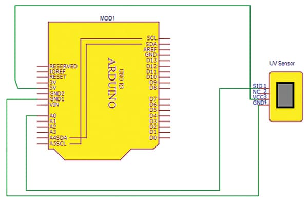
UV Radiation Testing Device – Circuit Diagram
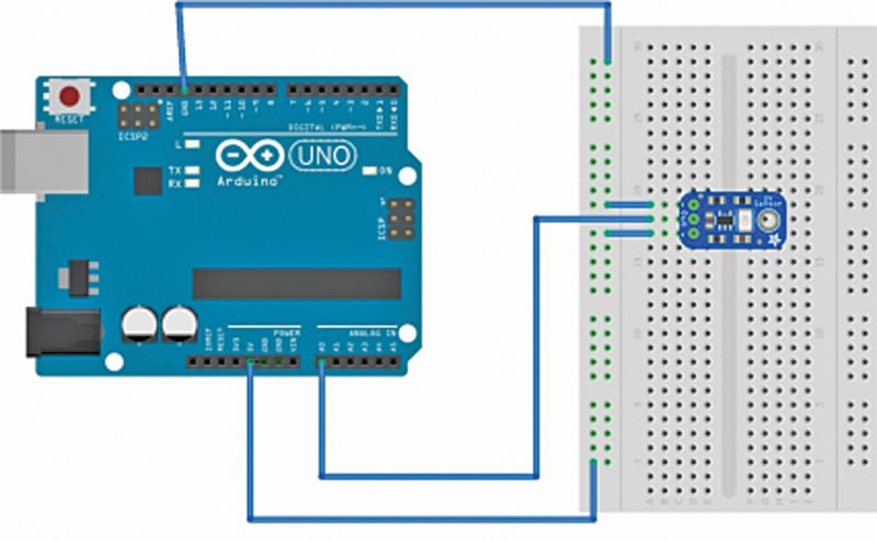
The circuit diagram of the project is shown in Fig. 6. After getting the components, connect them according to the wiring diagram (Fig. 5). Pin connections for both the UV sensor and Arduino are described in Table 2.
| Board Labels and Pin Functions of Arduino Uno | ||
| Connections UV Sensor (CJMCU-GUVA-S12SD) and Arduino UNO | ||
| Board Label | Pin Function (UV Sensor) | Arduino Uno |
| GND | Ground | GND |
| 5V | 5V input | 5V |
| OUT | Output of the sensor | Pin A0 |
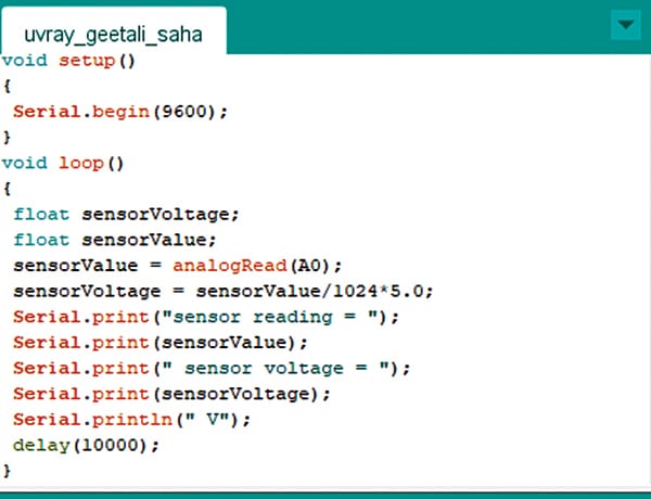
Install the latest version of Arduino IDE and connect the Arduino to USB. Now create the program for reading sensor data, wherein the loop function checks the analog value of the sensor. Fig. 7 shows the screenshot of the source code.
UV Radiation Testing Device – Testing
When the light rays emitted by any source fall on the photodiode of the UV sensor, they generate a value. This sensor value is read using the analog read command.
The corresponding voltage is evaluated, and both values are displayed on the serial monitor. The same sensor is tested with a smartwatch and a UV C lamp both. Fig. 8 shows the typical readings of the smartwatch.

The UV C lamp used for testing is a special-purpose lamp that is generally targeted toward sanitization tasks. Its specifications are:
Bulb shape size: A21
Bulb base: E27
Incandescence: 4,000 kelvin
Brightness: 22,500 lumens
Power: 250 watts
Average life span: 5,000 hours
Fig. 9 shows the typical readings with the UV-C lamp.

In conclusion, smartwatches emit UV rays in the range of 0-2 UV index, which is the range of a minimal danger zone and is not considered harmful to humans.
Check out more such interesting Arduino Projects.
Dr. Geetali Saha is a faculty in the Department of Electronics and Communication Engineering, GCET, Anand, Gujarat, and Parth Shah from 3rd Year IT Engineering department is her lead student coordinator working on this sponsored project
Great post.