


- Simple Overflow Stopper For Water Tanks
- Stop Tank Overflow With Wireless Water Level Indicator and Controller
- Water Level Indicator Circuit (LED based)
- Water Level Indicator using 7-Segment Display
- Wireless Water Level Monitoring and Pump Control System
- Automatic Water Pump Controller
- Smart Water Meter To Help Control Water Wastage
- Water Level Detection and Alert System Using Arduino
- Ultrasonic Liquid Level Monitoring System Using MATLAB
 Water is a vital but scarce natural resource. To prevent water wastage, this water tank overflow indicator comes in handy. It gives audio as well visual alarm whenever the water tank overflows.
Water tank overflow indicator circuit
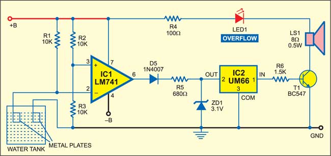
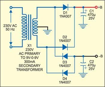
Fig. 1 shows the water tank overflow indicator circuit and Fig. 2 shows the power supply circuit.
In the power supply unit, mains AC is stepped down by transformer X1 to deliver secondary output of 9V-0-9V AC at 300 mA. The transformer output is rectified by a full-wave bridge rectifier comprising diodes D1 through D4 and filtered by capacitors C1 and C2 to provide +9V at ‘+B’ point and –9V at ‘–B’ point. Connect ‘+B,’ ‘–B’ and ‘GND’ terminals of the power supply unit to the respective terminals of the water-tank overflow indicator circuit.

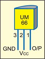
The circuit is built around op-amp LM741 (IC1), which is used as a comparator. The pin configuration of melody generator IC1(UM66) is shown in Fig. 3.
When water in the tank is below the metal plate sensors, inverting pin 2 of IC1 is at a higher potential than non-inverting pin 3. Output pin 6 of the op-amp is low and there is no music from programmable melody generator IC UM66 (IC2). Transistor BC547 (T1) remains cut-off and therefore LED1 doesn’t glow and the loudspeaker remains silent.
Circuit operation
When water in the tank touches the metal plate sensors, it extends ground to pin 2 of IC1. Now pin 3 of IC1 is at a higher potential than pin 2. The high output of the op-amp generates 3.1V across zener diode ZD1. Melody generator IC2 produces a melody, which drives the transistor to light up LED1 and sound an alarm from the loudspeaker. Rectifier diode D5 is used to prevent negative polarity to the cathode of the zener diode.
Water Level Monitoring and Control Projects
- Simple Overflow Stopper For Water Tanks
- Stop Tank Overflow With Wireless Water Level Indicator and Controller
- Water Level Indicator Circuit (LED based)
- Water Level Indicator using 7-Segment Display
- Wireless Water Level Monitoring and Pump Control System
- Automatic Water Pump Controller
- Smart Water Meter To Help Control Water Wastage
- Water Level Detection and Alert System Using Arduino
- Ultrasonic Liquid Level Monitoring System Using MATLAB

I WANT TO MAKE THIS PROJECT WITH VOICABLE(HUMAN )INSTEAD OF MUSIC..PLEASE EXPLAIN…
Instead of melody sound I want to make talking alarm how to make this
If the sensor part that is the two metal plates are kept in the overhead tank and joined with copper wire to the circuit which I want to keep on the ground floor and is about 50 feet away from the overhead tank, in that case will the circuit work? Please reply.
We have got 3.3v zener diode available in our local market, will that do instead of 3.1v zener diode??
If the sensor part that is the two metal plates are kept 50 feet away in the overhead tank and the circuit are kept in the ground floor and connected by copper wire, will the circuit work??
What is difference between ground and negative terminal.
Can we connect both if separate ground is not available
The common return path in a circuit is informally called ground ( or GND in short), even though it is not actually connected to ground or earth. Sometimes people get confused with GND and negative terminals. For e.g. the negative terminal of a battery source also connected to ground but this may not be always the case. If a circuit is designed for dual power supplies (e.g. LM741 in this case), the ground and negative terminals are different. So, you cannot tie both negative and GND terminals together in this case. Here, you need two 9V DC sources. First 9V supply, with its +Ve terminal connected to +B and -ve terminal to GND in the circuit. Second 9V, with its -ve terminal to -B and +ve terminal to GND in the circuit.