
This Arduino cloud-based IoT toy car can be controlled remotely using a smartphone, tablet, or laptop connected to the internet. The design can also be extended for applications such as sensor data collection and cloud-based monitoring. Built around the IndusBoard Coin, the system is both compact and lightweight.
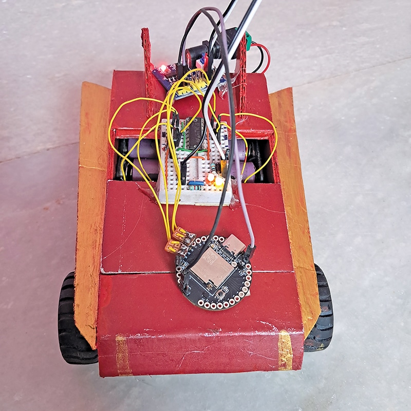
The Arduino IoT Cloud acts as the wireless remote-control platform, enabling commands to be transmitted and received over the internet. Fig. 1 shows the author’s prototype. The car is driven by N20 DC motors through an L293D motor driver IC, while the IndusBoard Coin connects to the Arduino IoT Cloud to receive, process, and execute control commands, driving the motors accordingly. The components required to build the system are listed in the Bill of Materials
in Table 1.
| Table 1 Bill of Materials | ||
| Material | Description | Quantity |
| N20 DC gear motor | Motor 1, motor 2, motor 3, motor 4 | 4 |
| N20 wheels | Wheels for motors | 4 |
| IndusBoard Coin | Controller board (programmed with code) | 1 |
| Connector wires | Interconnection wiring | As required |
| Switch | Power on/off control | 1 |
| L293D | Motor driver IC | 1 |
| 6V battery | Power supply | 1 |
POC Video Tutorial
Prerequisite configuration
Create an account on Arduino IoT Cloud and sign in. Then create a new Thing, configure the required variables, generate and edit the sketch, and upload it to the board. Next, create a dashboard and add the necessary widgets to monitor and control the device.
To operate the device remotely, install the Arduino IoT Remote app from the Google Play store and sign in using the same Arduino account. The system can also be controlled via the Arduino IoT cloud dashboard in a web browser. The setup process involves the steps mentioned below.
To create a thing and variables in Arduino IoT Cloud:
- Log in to Arduino IoT Cloud and create a new thing.
- Connect the IndusBoard Coin to a computer using a USB cable and set it as the associated device.
- Select ESP32 as the device type and ESP32S2 dev module as the board.
- Save the generated device key, as it will be required later for authentication.
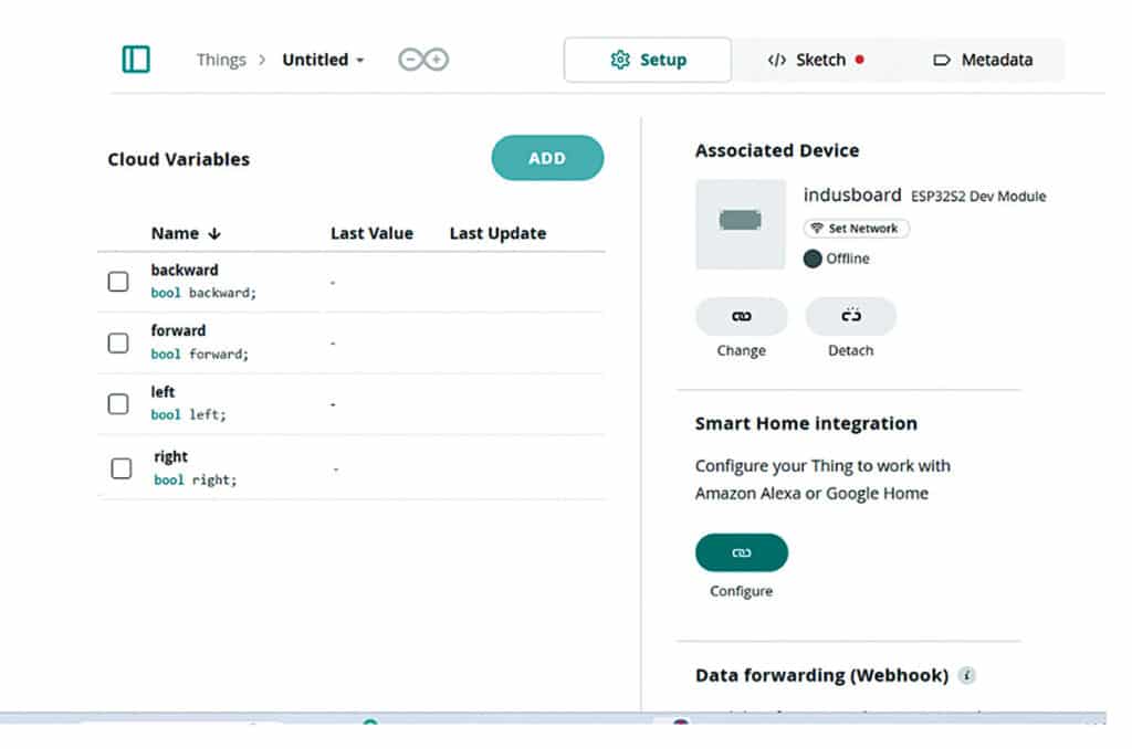
- Create four cloud variables named forward, backwards, left, and right, each with the Boolean (bool) data type.
- Set the permissions for all variables to Read & Write and the update policy to On change. Fig. 2 shows the Arduino IoT Cloud configuration used for this system.
To configure the device, follow the steps mentioned below:
- Select the target board (ESP32S2 dev module).
- Enter the Wi-Fi SSID and password under the network settings section.
- Save the configuration.
Next, generate and modify the sketch through following steps:
- Open the sketch tab in Arduino IoT Cloud to automatically generate the system code.
- Open the generated thingProperties.h file and verify the Wi-Fi credentials and device key.
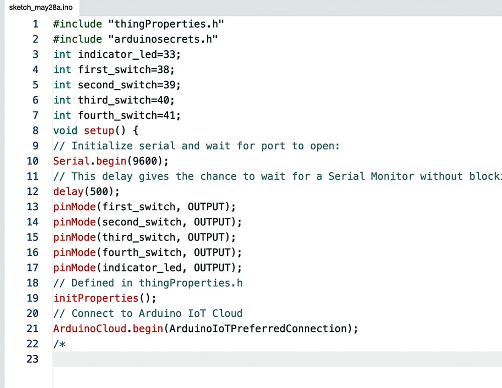
- In the callback functions, such as onForwardChange(), onBackwardChange(), onLeftChange(), and onRightChange(), add the necessary control statements to drive the motor control pins. Fig. 3 shows the relevant code snippet.
Now, to configure the dashboard, navigate to the dashboards tab and create a new dashboard. See Fig. 4 showing the IoT Cloud dashboard.
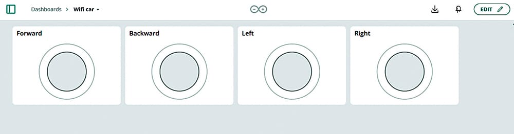
Click Addwidgets and select the push button widget for the forward variable; repeat the same for backward, left, and right by linking them with each other’s widget, respectively.
Repeat this three more times until there are four push button widgets on the screen.
Circuit and working
The circuit is built around an IndusBoard Coin (an ESP32-based controller), an L293D motor driver IC, four DC geared motors connected as two motor pairs, and a 5V-6V battery supply.
The IndusBoard Coin provides Wi-Fi connectivity and generates the control signals required to operate the motors through the L293D motor driver. The L293D functions as a dual H-bridge motor driver, allowing the low-current GPIO pins of the IndusBoard Coin to control higher-current DC motors.
Digital pins 38, 39, 40, and 41 of the IndusBoard Coin are connected to the IN1, IN2, IN3, and IN4 input pins of the L293D, respectively. These inputs determine the direction of motor rotation. Fig. 5 shows the circuit diagram of the Wi-Fi-controlled robot car, which uses the IndusBoard Coin, an L293D motor driver, and four DC geared motors.
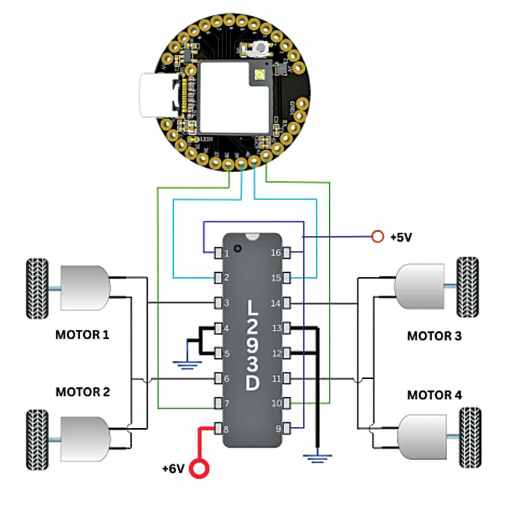
The ENA (pin 1) and ENB (pin 9) enable pins of the L293D are connected to the +5V supply, keeping both motor channels continuously enabled. The logic supply, VCC1 (pin 16), is connected to +5V, while the motor supply, VCC2 (pin 8), is powered from a 5V-6V battery source.
All ground terminals of the IndusBoard Coin, L293D, and battery are connected together to establish a common reference.
The left-side motor pair is connected across OUT1 (pin 3) and OUT2 (pin 6), while the right-side motor pair is connected across OUT3 (pin 11) and OUT4 (pin 14). Fig. 6 shows the interface between the IndusBoard Coin and the L293D motor driver for controlling the robot car’s left and right drive motors.
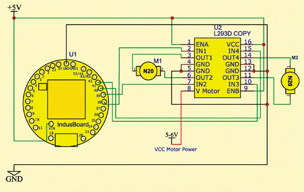
When a control command is received from the Arduino IoT Cloud dashboard, the IndusBoard Coin processes the command and accordingly changes the logic levels on pins 38, 39, 40, and 41. These signals are applied to the L293D, which drives the motors in the required direction.
When the forward command is selected, both motor channels rotate forward, moving the robot forward. For backward movement, both motors rotate in reverse. During a left turn, the left motor is stopped or reversed while the right motor continues rotating, causing the robot to turn left. Similarly, during a right turn, the right motor is stopped or reversed while the left motor continues rotating.
The ESP32’s built-in Wi-Fi capability allows remote control of the robot through the Arduino IoT Cloud interface from anywhere with internet access.
Construction and testing
First, upload the Arduino IoT Cloud program to the IndusBoard Coin and ensure that it compiles and uploads successfully.
Connect the L293D logic supply to +5V and the motor supply to a 6V battery, ensuring a common ground connection throughout the circuit.
Securely mount the geared motors, wheels, battery holder, IndusBoard Coin, and L293D module to the robot chassis, and arrange the wiring neatly. The completed system is shown in Fig. 1.
For testing, allow the IndusBoard Coin to connect to the configured Wi-Fi network. Open the Arduino IoT Cloud dashboard on a smartphone or computer and confirm that the device is online.
Use the Forward, Backward, Left, and Right controls to verify the robot’s movement. If a motor rotates in the wrong direction, interchange its terminals. Perform a final movement test on a flat surface to ensure smooth operation in all directions.
The robot can be controlled from the Arduino IoT Cloud dashboard using a web browser or the Arduino IoT remote mobile app. Table 2 shows the dashboard controls and their corresponding functions.
| Table 2 Arduino IoT cloud dashboard controls | ||
| Dashboard element | Function | IndusBoard Coin pins |
| Forward push button | Forward movement | 39, 40 |
| Backward push button | Backward movement | 38, 41 |
| Left push button | Left turn | 38, 40 |
| Right push button | Right turn | 39, 41 |
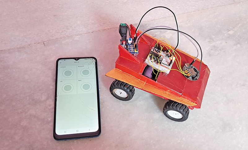
The dashboard provides four push-button controls for robot navigation. The forward and backward buttons move the robot forwards and backwards, respectively, while the left and right buttons control turning. The corresponding IndusBoard Coin pin combinations are listed in Table 2. These controls enable wireless operation of the robot through the Arduino IoT Cloud platform. Fig. 7 shows the testing setup with the prototype and mobile phone.
The author Hemant Padval is an electronics hobbyist