Building upon the author’s previous article on product risk analysis, this article delves into the often overlooked link between design and manufacturing, where poor design choices can lead to costly issues. The article explores how measuring process complexity and reducing intricacies can empower the product development process.
In 1957, The Michigan Technique—a renowned magazine focussing on machine tools and production techniques—published a poem that humorously depicted the ongoing struggle between designers and the shop floor.

The poem highlights the changes made by the designer and concludes with the lines:
“And it can’t be planned and it can’t be ground
So I feel my design is unusually sound.”
And he shouted in glee,
“Success at last!
This goddam thing can’t even be cast.”

Unfortunately, this satirical portrayal reflects a reality that we often overlook. Countless examples surround us, demonstrating how poor design has resulted in costly manufacturing and maintenance issues. With a few clicks of a mouse, a design can be altered.
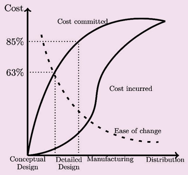
However, once the manufacturing stage begins, any modifications to the product design become very costly.
Extensive research has revealed that we commit about 63% of the cost at the time of initial design conception. By the time the design is finalized, approximately 85% of the costs have already been committed (Fig. 1).
Subsequent processes of manufacturing and distribution offer little room for improvement.
During the design phase, it is crucial to consider manufacturing operations. There are two main aspects of manufacturing problems. One type of problem arises from manufacturing complexity.
These complexities may emerge due to the different types of components required for creating the parts.
Larger varieties require more inventory holding and more effort in supply chain management. We can also have complexities from a large number of different processes required to make the product.
Process complexities can arise from the diverse range of machines, storage, handling systems, and operators involved.
Managing and maintaining the various storage and handling systems can pose challenges and the training required to operate them increases accordingly.
If we do not train the people properly on using different tools and equipment, the whole purpose of creating variety gets defeated.
Without proper training, people end up misusing the equipment. In such cases, the special feature becomes more of a hindrance than a tool.
There is a third kind of complexity, that is the operational complexity. Operational complexity arises from difficulty in operating. Certain designs require operators to perform risky or complicated procedures to make the product.
We need to design our product to reduce all these three types of complexities as much as possible to make it manufacturable.
| Circuit Complexity Calculation: | |||||
| Item | n | N | Div. Ratio | Entropy | Comp Index |
| ICs | 3 | 3 | 1 | 2 | 2 |
| Pre-assembled modules | 2 | 2 | 1 | 1.585 | 1.585 |
| PCBs | 2 | 2 | 1 | 1.585 | 1.585 |
| PCB connectors | 2 | 2 | 1 | 1.585 | 1.585 |
| Diodes | 3 | 5 | 0.6 | 2.585 | 1.551 |
| Resistors | 4 | 11 | 0.364 | 3.585 | 1.304 |
| Transistors | 2 | 4 | 0.5 | 2.322 | 1.161 |
| Capacitor | 1 | 1 | 1 | 1 | 1 |
| Buzzer | 1 | 1 | 1 | 1 | 1 |
| Relays | 1 | 2 | 0.5 | 1.585 | 0.792 |
| Current sensors | 1 | 2 | 0.5 | 1.585 | 0.792 |
| Total | 14.355 | ||||
Measurement of Process Complexity
We need to measure things that we want to control. Without measurement, we cannot gauge our current status and determine the direction in which we are heading.
However, measuring complexity presents a challenge since it is an intangible property. We can understand when something is complex but there is no way to measure complexity directly.
To overcome this challenge, researchers have developed surrogate measures that indicate the level of complexity. There are quite a few such indirect measures.
One such method is the complexity index (CI) calculation proposed by H.A. EIMaraghy, which is based on information theory. Instead of delving into the mathematics behind it, let’s focus on how to use it in practice.
ElMaraghy’s index is easy to use. It allows us to compute the CI of individual subsystems and then add them together to determine the total complexity.
We can calculate complexity as:
System Complexity: Is=I1+I2+ …+Im, where m is the total number of subsystems
Subsystem complexity: Ix=Dx×Hx
Diversity ratio: Dx=n/N, where n is the number of unique items in the xth category and N is the number of total items in that category
Entropy: Hx=log2(N+1). Note that here we use the log of base 2.
Let us compute the complexity of the circuit we designed in our previous article. We count the total number of each of the different types of items and their varieties. Then we use the formulas to compute the complexity index (Table 1).
Individual CIs give us an idea of where to look for complexity reduction. Normally, there is a better scope of improvement where we have a large CI as well as a large N.
Although we have yet to design the manufacturing facilities, we will employ this process to assess the complexities of these facilities as well.
Reducing Part Complexity
The best way to reduce complexity is to eliminate unnecessary parts. Eliminated parts do not need to be designed, produced, purchased, tested, stocked, assembled, and disposed of.
They will never be rejected, cause production delays, become obsolete, or get lost, requiring write-offs.
To determine whether a part is truly required, we should ask ourselves nine questions:
- Does the part move relative to the others?
- Is the movement essential for the product to function?
- Must the part be separate for the required movement?
- Is the part made of a different material or isolated from the rest?
- Is this different material or isolation essential for the product to work?
- Must the part be separate for the required isolation or material?
- Do we require the part to be separate for in-service adjustments or replacements?
- Is the adjustments or replacement essential?
- Must the part be separate for the adjustment or replacement?
We should allow separate parts only when the answer to all these nine questions is yes. In some cases, we may have to keep a part separate for reasons of market availability or modularity. In such cases, we should mark the part as a non-essential part.
Once we start questioning in this manner, we will find many avenues for reducing parts. For instance, in our case, we decided to use separate PCBs for the relays and the control circuit.
The critical analysis shows that we need not have separate PCBs during manufacturing. Instead of managing two parts, we can use one PCB during manufacturing and separate the PCBs after the components are assembled.
In addition, instead of using four different transistors, we can use a single integrated transistor IC that has four transistors.
The proper selection of microcontrollers can also help reduce part count. In mechanical parts, we can use flexible components to provide relative movements between parts instead of keeping them separate.
Also, choosing appropriate fits and tolerances contributes to the reduction of part counts. Innovation plays a vital role in simplifying the design.
Operational Complexity in Manufacturing
Operational complexity stems from the difficulty in storage, handling, and assembly of the product. We have already discussed the complexity determination of storage and handling. Within the workstation, we encounter various difficulties during assembly.
There is a systematic process, originally invented by Cummins, to analyze and reduce assembly complexity.
Correct Fitting: Every part has some dimensional tolerances. If we use parts that have opposing tolerances, assembly may become difficult. This challenge becomes more significant if the part interfaces with many other parts.
Ideally, the main part should have only one interface with the components. When this is not the case, assembly difficulties arise. Our goal should be to minimize the number of parts and the number of interfaces.
The assembly complexity index (ACI) gives an idea of assembly difficulty. If N is the number of parts and IX is the number of interfaces of xth part, then ACI is calculated as:
ACI=√(NΣIx)
Ideally, the number of parts should be the same as the theoretical minimum number of parts NT and the number of interfaces should be 2(Nt–1). We can compute our target ACI as:
ACIT=√[N
ACIT=√[NT×2(NT–1)]
We can compare how far we are from the target and work accordingly. Normally, if we are within 80% of the target value, it is a good design.
Wrong Assembly: During assembly, operators may omit some parts, they may fit the wrong parts, or misorient the parts. A robust manufacturing system will ensure that only the correct part is presented for assembly. It will also flag a warning or alarm if some parts are missing.
There are many ways to detect missing components. The easiest is to compare the assembled item with a standard reference. Visual inspection often detects missing components easily.
Alternatively, we can verify if all the parts are picked up during the assembly.
Well-designed components can help prevent the wrong assembly. Designers should try to make components symmetrical that can be assembled without bothering about correct alignment.
Alternatively, designers can make parts asymmetrical so that they will only mate when aligned correctly.
Handling: Difficulty in handling components creates difficulty in assembly and will require special attention and tools. There are three kinds of difficulty in handling.
Entanglement: Parts like spring and circlip get entangled in storage bins. During assembly, the operator must take out and loosen the parts to assemble them.
Keeping the parts in separate sleeves or making some changes in design helps to avoid entanglement. If we close the ends of the springs, they do not get entangled.
Some parts, especially those that are shaped like paper cups, tend to get into each other and require some force to separate. In most cases, such nesting can be avoided by redesigning the parts.
Grasping: Slippery parts, parts with sharp edges, fragile parts, or flexible parts are difficult to grasp. The operator must pay special attention to their assembly. It is best to have some facility to make such parts drop automatically instead of handling them.
Too small: Parts that are less than 3mm in size require the use of tweezers and magnifying glasses to handle.
Insertion: When operators have to insert a component into another for assembly, they will need to spend more time. Common problems encountered during insertions include:
Difficulty in alignment or locating: Long screws, rods, pins, etc are difficult to insert into narrow holes. They require special attention. Consider incorporating design features like chamfers or guides for the part to fall in the correct place.
Necessity to hold down the part: While assembling multiple loose parts, or when a part is to be compressed, the operators may have to hold down the parts. Such a problem may also happen while applying glue or solder.
Holding down impedes the maneuverability of the tool and makes the job difficult. Explore the use of some fixtures or other mechanisms to avoid the need for manual holding down during assembly.
Having resistance during insertion: Parts that require press fitting or hammering for assembly fall into this category. Not much can be done when we need to apply force during assembly. One must re-examine the need for such force.
Obstruction to access or visibility: Assembling parts blindly, where the operator must work using his sense of touch, is a big challenge. Such requirements can be avoided by holding the job from a different angle. Alternatively, the parts may be redesigned to avoid blind assembly.
Secondary Operations in Product Assembly
Normal assembly of a product consists of pick and place operations. If the operator must do something other than pick and place, it is called secondary operation.
Secondary operations require extra effort. We should try to eliminate them as much as possible.
Secondary operations can be classified as:
Reorientation: When assembly requires turning the job, or the job needs to be put into a special fixture, it is called reorientation. Reorientation is a possible source of misalignment. It also requires extra work.
We must design parts in such a way that they can be assembled in one set-up. At times, when such assembly is not possible, we can explore making sub-assemblies beforehand and then combine the sub-assemblies in one place.
Fastening: Fastening components using screws, rivets, crimping, or twisting require additional work. If drilling is involved to facilitate the placement, it is even more work.
We should avoid these features to fasten components and instead try design options that allow for interlocking components by placement. Using a magnetic lock, snap lock, and Velcro are better options than screws and rivets.
Fusing: Fusing two parts by welding, soldering, or gluing can provide a better option than screws, where parts are fixed in their place permanently. These options for fusing also involve additional work. We should look at the option to automate it.
Filling: Applying lubricants, filling gas, or some other liquid can be problematic work during assembly. Whenever possible, try to avoid or automate such operations.
Testing: Testing or adjusting products during or after assembly often can be necessary but time-consuming. There are two ways to avoid this step. One is to improve the reliability of the processes and monitor them closely by using the 6-sigma methodology to avoid final product inspection. The second option is to automate the procedure.
In my opinion, both options are mutually exclusive. They should be practiced together, depending on the level of process capability.
Assembly Indices
Apart from the assembly complexity index we discussed earlier, some other indices tell us about the quality of our design from a manufacturing and assembly perspective.
These indices are:
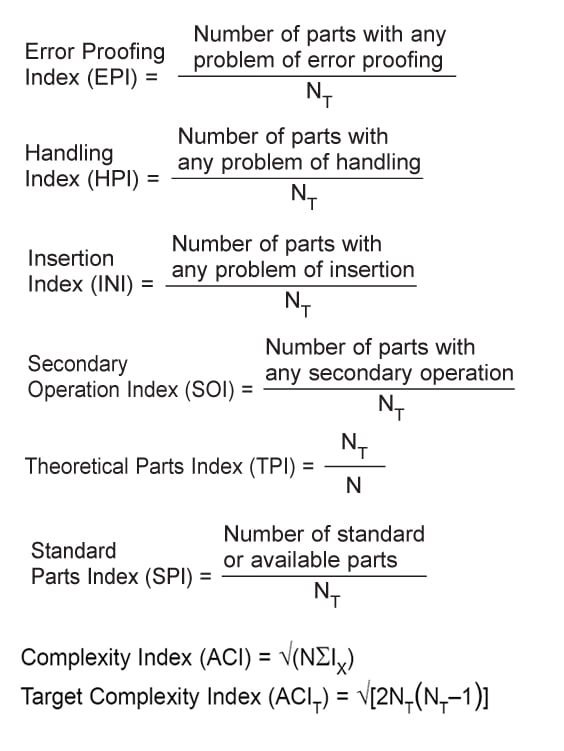
Systematic DFMA Analysis
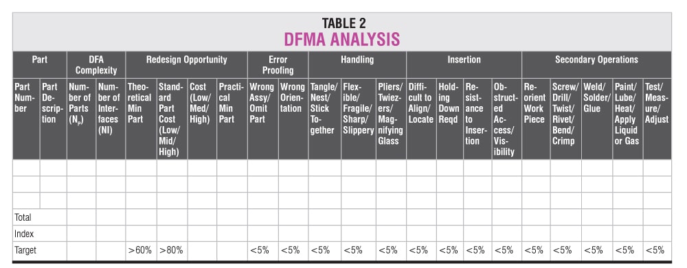
Systematic evaluation of different bottlenecks in assembly helps us to find the problem areas and focus on innovation to solve them. For the DFMA analysis, the chart given in Table 2 is a valuable tool.
We start our analysis by listing down all the parts that go into the assembly. We first evaluate the essential parts and identify the possibility of reducing the parts.
If we are better than 60% in TPI and better than 80% in SPI, we can be satisfied and move to other areas.
Next, we should look at the assembly complexities. A high ACI means we shall face difficulties during assembly and have more quality problems in assembled products. High ACI will also require us to make parts with close tolerances.
Normally, if we are within 120% of the target ACI we can say that design is good.
Once we have done the assembly complexity analysis, we should evaluate other process indices. To analyze handling, error proofing, insertion, and secondary operation problems, we check each part against the checklist and mark a tick or ‘y’ for cases where there is a problem.
Finally, we calculate the percentage of such cases against theoretical minimum parts.
For the areas where we have problems in more than 5% of parts, we must review the assembly process and design of the parts to bring the problem cases down.
Design Guidelines for Assembly
Always thoroughly examine the need for designing a new part. In most cases, we can design products using readily available standard parts.
If standard parts do not serve our requirements, we should examine the possibility of using parts that are already designed for some other product.
Reusing parts helps us to avoid additional manufacturing setup as well as reduces the time required to develop a new part. Sometimes, it may be possible to reuse an existing design with slight modifications.
For ease of assembly, the product must have a base part where all other parts will fit. In cases where multiple such parts compete for the base part, we can think of making sub-assemblies separately and then assembling the main product.
We must remember and distinguish between essential parts and non-essential parts. Parts like fasteners, spacers, washers, O-rings, connectors, leads, pipes, and circlips are not what a customer sees as a product.
They may be important for technical reasons but they have no value for the customer. Try to eliminate these non-essential parts.
Of the non-essential parts, a screw is probably the most troublesome one. Screws are a century-old technology. They are difficult to locate and difficult to fix. After repeated use, screw threads wear out and become a maintenance problem.
A study by Ford Motor Co. revealed that threaded fasteners were the most common cause of warranty repairs. A similar finding has been echoed in other surveys as well. Use screws in a product only as a last resort. If you are fastening or gluing some parts, then examine the possibility of combining them.
Cost-wise, screwing is the costliest option for fastening, followed by riveting, plastic bending, and snap-fit in decreasing order. If we must fasten two components, examine the possibility of using snap-fitted parts.
Symmetrical parts are always oriented properly. If the product requires a part to be asymmetrical, make sure that part can only be fitted with the correct orientation.
Gravity helps to keep the parts in place. If we ensure that parts can be stacked from the top, gravity becomes our friend, and during assembly, the parts will remain in place when we place them on top of another part.
If we try to assemble anything from the bottom, it becomes a very difficult operation.
Provide features to guide the parts to be assembled into their correct place. Features like counter sinking, recess, and projection help to guide components in their correct location.
Consider handling difficulties during assembly. Closing spring ends, using flanges, and avoiding sharp locking angles ensure that parts will nest or tangle in the storage bins.
Try to avoid restricted access during assembly. Try to keep the base part, where most other parts will be assembled, open from all sides. This will help free access to tools during assembly. Ensure that operators will be able to see the parts clearly during the assembly process.
To summarise:
- Minimise part count
- Design parts that are self-locating
- Design parts that are self-fastening
- Minimise reorientation of parts during assembly
- Design for component symmetry to minimize reorientation
- Design parts for easy retrieval, handling, and insertion
- Plan for fault-proof assembly
- Use drop-down assembly that makes gravity a friend
- Standardise parts and reuse parts already designed
- Encourage modular design
- Plan for a base part to locate other components
By embracing simplicity and efficiency in our designs, considering manufacturing operations, and utilizing measurement techniques like the ElMaraghy complexity index, we can unlock the potential for improved manufacturability, reduced costs, and successful product realization.
Soumyanath Chatterjee is former TVS Motors Chair Professor at Industrial and Systems Engineering Department, IIT Kharagpur. His expertise is in Product Development and Supply Chain Management