Supercapacitors are energy storage devices that bridge the gap between electrolytic capacitors and rechargeable batteries. This article explains their importance and usage in defence and transportation sectors.
Electricity is a hugely versatile form of energy, but it suffers one major drawback; it is relatively difficult to store. Batteries can store large amount of power, but they take hours to charge up. Capacitors, on the other hand, charge almost instantly but store only tiny amounts of power.

In the next few decades, our fossil-fuelled cars and home heating appliances will need to be switched over to electric power, if we are to avert catastrophic climate change. Besides, in modern-day defence equipments, there is a need to supply high energy electric pulse. In our electric-powered future, where we will be required to store and release large amounts of electricity very quickly, it is quite likely we will turn to supercapacitors that combine the best of both the worlds.
What is a supercapacitor?
The structure of a capacitor is rather simple. It consists of two electric conductors called plates and an insulating layer between them called dielectric medium. If these two plates are connected to direct voltage, they become charged, and the magnitude of electric charge accumulated on the plates becomes proportional to the magnitude of voltage. The more charge it takes when voltage is applied, the higher the capacitance is. A supercapacitor is different from an ordinary capacitor mainly in two important ways—its plates effectively have a much bigger area and the distance between them is much smaller because the separator between them works in a different way than a conventional dielectric.
Like an ordinary capacitor, a supercapacitor also has two plates that are separated. The plates are made of metal that is coated with a porous material like activated carbon, which provides the plates effectively with a bigger surface area, rendering it to store much more charge. For better understanding, let’s assume electricity as water—where an ordinary capacitor is like a cloth that can mop up only a tiny little spillage of water, while a supercapacitor’s porous plates can soak up many times more because they are more like a chunky sponge. Porous supercapacitors are big electricity sponges.
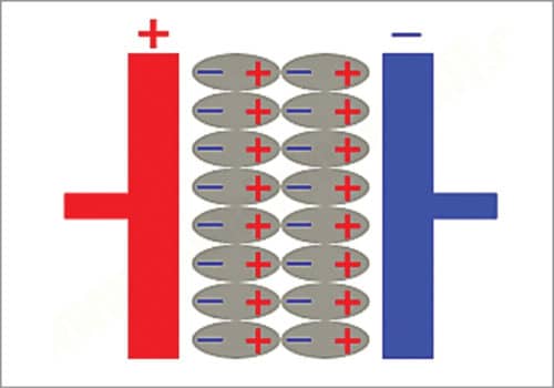
In an ordinary capacitor, the plates are separated by a relatively thick dielectric made of mica or plastic, or even simply air. When the capacitor is charged, positive charges form on one plate and negative charges on the other plate, creating an electric field between them. The field polarises the dielectric, so its molecules line up in the opposite direction to the field and reduce its strength. That means the plates can store more charge at a given voltage. This is shown in Fig. 1.
Classification of supercapacitors
Supercapacitors are mainly classified into three types: Double-layer capacitors; Pseudo-capacitors; Hybrid capacitors.
Double-layer capacitor (DLC)
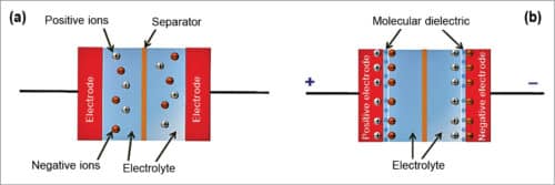
A capacitor consists of two electrodes, separator and electrolyte. As shown in Fig. 2, in a double-layer capacitor (DLC) there is no dielectric as such. Supercapacitors are often termed as DLC. The electrolyte in a DLC is the mixture of positive ions and negative ions dissolved in a solvent. Both the plates are soaked in an electrolyte and separated by a very thin insulator made of carbon, paper or plastic.
When the plates are charged up, an electrical double layer appears at the interface between a conductive electrode and an adjacent liquid electrolyte. At the boundary, two layers of charge with opposing polarity are formed, one at the surface of the electrode and one in the electrolyte.
These two layers are typically separated by a single layer of solvent molecules (generally one molecule thick) that adhere to the surface of the electrode and act like a dielectric as in a conventional capacitor. The solvent molecules act as a barrier and prevent combination of opposite charges. Therefore no electric charge flows in between electrode and electrolyte. In conventional capacitor, the thickness of dielectric might range from a few microns to a millimetre or more.
In short, supercapacitors get their much bigger capacitance from a combination of plates with a bigger surface area and less distance between them (because of the very effective double layer). The supercapacitor’s capacitance is in direct proportion to the area of electrical double layer.
Upon voltage application, the electrical double layer is created that aligns both negative and positive charges along the boundaries of electrodes and electrolytic solution. When these negative or positive ions migrate close to the electrode, they experience strong opposition from the solvent molecules. Hence, no charge transfer takes place between electrolyte and electrode.
However, these opposite charges exert electrostatic forces on each other. Thus, a large amount of charge is built up at the common boundary of electrode and electrolyte. The activated carbon layer deposited on the electrodes is very much porous and provides astounding surface area and acts as a storehouse for storing electric charges during charging.
Pseudo-capacitor
A pseudo-capacitor is a hybrid between a battery and electric double-layer capacitor. It also consists of two electrodes separated by an electrolyte. Charge storage occurs by chemical and electrostatic means. The chemical process involves charge transfer by means of reduction-oxidation that is redox reaction when most of the charge is transferred near the surface of the electrode.
On the other hand, in double-layer capacitors, positive and negative charges reside on two electrode surfaces. While the charge transfer is similar to that in a battery, transfer rates are higher because of the use of thinner redox material on the electrode, or lower penetration of the ions from the electrolyte into the structure.
Because of multiple processes acting to store charge, the capacitance values are higher. Pseudocapacitance is accompanied by an electron charge transfer between electrolyte and electrode coming from a de-solvated and adsorbed ion. The adsorbed ion has no chemical reaction with the atoms of the electrode since only a charge transfer takes place. It uses transition metal-oxides like RuO2, IrO2, or MnO2 inserted by doping in the conductive material like active carbon, which covers the electrode. Both pseudocapacitance and double-layer capacitances contribute inseparably to the total capacitance value.
Hybrid supercapacitor
Hybrid supercapacitors are the devices with elevated energy storage capability and elevated capacitance. It combines electric double-layer capacitor and lithium-ion technology, resulting in an energy density up to 115 per cent higher. The hybrid capacitor offers an enhanced capability of energy storage, providing power to applications more quickly and efficiently.
Construction details
Electrodes
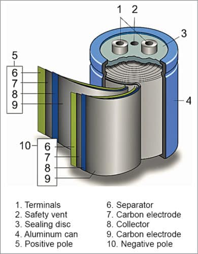
The internal arrangement of a wound type cylindrical supercapacitor is shown in Fig. 3. It comprises active layers made from activated carbon electrodes and separator with aluminium tabs inserted in-between active layers. Aluminium foils should be able to distribute a peak current of 100A, and act as the current collector. They are coated with activated carbon, which is electrochemically etched, so that the surface area of the material is about 100,000 times greater than the smooth surface. The electrodes are separated by a very thin ion-permeable separator made of porous polymeric films or woven ceramic fibres.
Virtually all supercapacitor manufacturers use activated carbon made from coconut shells as the active component of the electrode. During processing, the ash is removed and kept below one per cent, iron is kept below 100ppm and halogens are removed in order to have an extended cycle of operation. High porosity of this material can provide an electrode area up to 3000 sq. metre/gm. It can yield capacitance of 145 F/gm. Active material represents half the total cost of a supercapacitor. As the cost of activated carbon is cheaper, about ₹ 1050/kg, it is being widely used.
A carbon nanotube (carbon molecules with a cylindrical nanostructure) is another promising active material, but is quite costly to manufacture. Carbon nanotubes cost about ₹ 3500/kg, but have double the energy density, and therefore are used for special-purpose supercapacitors. The nanotube surface provides greater wettability and has high conductivity. It can yield capacitance up to 180 F/gm.
Graphene, a two-dimensional carbon monolayer, is another promising candidate whose cost varies from ₹ 350 to ₹ 2800/kg. But its fluffiness limits the energy density of a supercapacitor and can’t be competitive, unless a way is found to tightly pack it.
For pseudocapacitors based on Redox, Ruthenium dioxide yielding capacitance of 750 F/gm, Manganese dioxide, which gives capacitance of 350 F/gm, IrO2, etc are typically used as electrodes.
Electrolytes
Electrolytes consist of solvent and dissolved chemicals that dissociate into positive cations and negative anions. Aqueous acidic or alkaline electrolytes are used in supercapacitors with low specific energy and high specific power. Electrolytes with organic solvents are more expensive but can give a higher capacitor voltage of 2.7V.
Uses of supercapacitors
Vehicles
Supercapacitors are used in vehicles for regenerative braking. They have much higher power densities than batteries and can charge and discharge more rapidly. They also store much more energy as compared to conventional electrolytic capacitors. This makes them more suitable for capturing kinetic energy as a vehicle slows and release it for bursts of acceleration.
They don’t have the ability to store large amounts of energy, but they are high powered devices, primarily because the electrons can move back and forth very quickly.
Supercapacitors can provide extra power of up to 34hp and can be used to smooth out acceleration, bridging the gaps in power delivery that occurs when the mechanical transmission changes gear. This removes any jerkiness that would occur during a shift. As supercapacitors can charge and discharge symmetrically and in seconds, they make for an incredibly efficient means of providing a short but strong electric assist in a vehicle while driving. The supercapacitor is discharged during acceleration and recharged during braking, which means that a hybrid motor or an e-motor never lacks the power it needs during driving, ultimately increasing the efficiency of the vehicle.
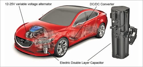
As shown in Fig. 4, the system generally uses a 12-25V variable energy alternator that generates electricity during regenerative braking at up to 25V before sending it to a low-resistance electric double-layer capacitor that can be fully charged in seconds. A DC-DC converter then steps down the electricity from 25V to 12V before distributing it to the vehicle’s electrical system.
Capa bus
A capacitor vehicle or capa vehicle, as shown in Fig. 5, is a traction vehicle that uses supercapacitors to store electricity. In general, supercapacitors can store about 5 per cent of the energy that lithium-ion rechargeable batteries can. This limitation restricts the range of driving to a couple of kms per charge. But they can be charged in a matter of seconds. So, in public transport systems such as buses that have to stop frequently at known points where charging facilities are installed, using supercapacitor as the energy storage device is quite viable.
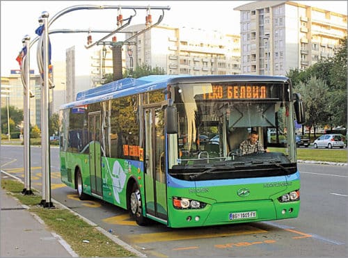
Since 2010, capa buses have been operating in Belgrade in Serbia, Shanghai, Hong Kong, Sofia, Bulgaria, and Graz in Austria without any major trouble. These buses are provided with supercapacitors made of activated carbon and have a typical energy density of about 10 watt-hours/kg compared to 200 watt-hours/kg of a high-performance Li-ion battery. These buses consume energy that is only one-tenth of the cost of fuel consumed by a diesel bus and can achieve lifetime fuel savings of about ₹ 15 million per bus.
The buses use 40 per cent less electricity, even when compared to an electric trolley bus, mainly because they are lighter. The capa bus is 40 per cent cheaper than a Li-ion battery bus and far more reliable. The buses need to stop regularly every 5km allowing quick recharging at charging stations at bus stops. A collector on top of the bus rises a few feet and touches an overhead charging line at the stop. Within a few minutes, the supercapacitor banks stored under the bus seats are fully charged. The buses also capture energy from braking.
The recharging stations can be equipped with solar panels. A third-generation bus has been developed, which can extend the range up to 32km. In the future, buses would use supercapacitors with vertically aligned carbon nanotubes as the active element that would have one-quarter of the energy density of a lithium-ion battery. Future developments include the use of inductive charging under the street to avoid overhead wiring.
Spot welding gun
Spot welding guns are generally used in the current robotic system in assembly lines for resistance welding of thin gauge steel (about 0.8mm). These machines use a pneumatic/electromechanically operated forcing system to apply force to electrodes and power supply to provide energy for welding. It weighs about 50kg including the weight of the transformer, which is about 25kg.
These welding guns are gradually replaced with supercapacitors based devices that result in a reduction in weight by 50 per cent due to elimination of bulky transformers. It yields a reduction in the cost of ₹ 7 million per unit and also reduces the scale of automation in the assembly line. These new generation machines are provided with supercapacitors up to a level of 5000 F and operate at a voltage less than 10V.
Defence application
Where to use supercapacitors in military devices? In applications where the charge can more or less be maintained continuously, but at times it is required to obtain enormous amounts of energy impulsively in a very short period of time. Supercapacitors already have set their foot in military technology.
Laser weapons (LaWs)
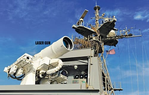
Laser weapons no longer exist only in science fiction. USA, Russia, China, and India have systems with which enemy aircraft, ballistic missiles, anti-ship ballistic missiles are destroyed with a laser beam. Onboard generator of the aircraft or ship provides electrical energy that is stored in the supercapacitor banks.
In case of a fast moving distant target like an enemy aircraft, missile, etc, it is not possible to hold the laser beam on the target. Therefore the energy that can destroy the target must be delivered in the form of single radiation of 10-100kW power pulse in a few milliseconds. Only supercapacitors have the capability of doing this task. Laser weapon systems are tied to ship or aircraft’s navigation radar and can be operated through the mother vehicle’s combat information centre.
A typical arrangement of LaWs is shown in Fig. 6.
Railgun
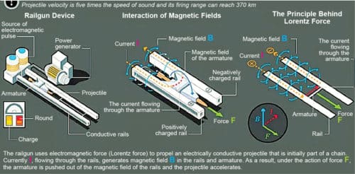
A railgun is a military device that uses electromagnetic force known as Lorentz force to launch projectiles 2m long and weigh 100-120kg at speeds exceeding Mach 7-8 using a sliding armature that is accelerated along with a pair of conductive rails. The projectile normally does not contain explosives, but relies on the projectile’s high speed to inflict damage.
The railgun uses a pair of parallel conductors, or rails, along which a sliding armature is accelerated by the electromagnetic effects of a current that flows down on one rail into the armature and then back along the other rail. It is based on principles similar to those of homopolar motor. However, the problem is that ships, like an aircraft carrier or destroyer, which can generate 25MW of power, are only suitable for its installation due to the high power requirement of the rail gun. The device uses supercapacitors to store the enormous power and deliver it as a pulse in a short period of time. Fig. 7 shows the arrangement of a railgun.
Heavy mobility truck
Heavy Expanded Mobility Tactical Truck (HEMTT) is an eight-wheel-drive, 9,100kg tactical truck with a 470hp diesel engine used by the US army and many other countries for transporting combat vehicles and weapons. This diesel-electric hybrid truck does not use batteries. Instead, it uses supercapacitors that accept more of the power created by regenerative braking and deliver the power to the wheels during acceleration. This increases efficiency by up to 20 per cent. This hybrid technology delivers up to 120kW of power to run an airfield, weapons, radar systems, hospitals, or a disaster relief command centre.
Pulsed linear accelerator weapon
It is a futuristic directed-energy weapon designed to work in such a way that if any enemy missile is launched towards a country, it will quickly emit powerful pulses of the relativistic electron beam, which is converted by other components of the machine down the line into flash x-ray and high power microwave that destroy the target. Unlike laser beams, it does not bore a hole in the target but thoroughly destroys the onboard electronic system.
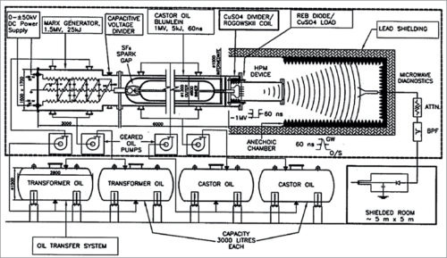
As shown in Fig. 8, the circuit generates a high-voltage pulse by a Marx generator by charging several capacitors (likely supercapacitors) in parallel by a DC power supply through the resistors and discharging them in series. The output is available as a brief pulse. USA, Russia, China, and India have this powerful weapon. India has developed this machine and christened it as KALI (Kilo Ampere Linear Injector) (refer Fig. 9). KALI 5000 system can produce electron pulses of about 100ns with energy of about 1MeV, current 40kA, a power of 40GW, and microwave radiation at 3-5GHz.

Rathindra Nath Biswas is a 1964-batch chemical engineering graduate from Jadavpur University, Kolkata. He was awarded a certificate for designing Benzol Plant by Giprokoks, USSR, and Certificate of Honour by Indian Institute of Metals. He has published 35 research papers in various journals. He retired from service as head – MECON, Durgapur.