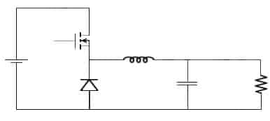
A buck converter (step-down converter) is a DC-to-DC power converter used to step down voltage, while stepping up current. It is a type of switched-mode power supply (SMPS) comprising of two semiconductors components, and an energy storage element. Capacitor based filters are usually added to reduce voltage ripple. These are added at either the input (supply-side filter) or the output (load-side filter).
These are also more efficient compared to linear regulators. Linear voltage regulators are much simpler circuits power efficiency as DC-to-DC converters than linear regulators, which are simpler circuits that lower voltages by dissipating power as heat, but do not step up output current. These are highly efficient hence are very useful in power conscious applications like mobile devices.
Buck converter circuit

The current in the indicator is controlled by two switches. Ideally, the switches have zero voltage drop when ON & zero current flow when off, with no resistance across the inductor. In the above circuit, the MOSFET is used as the switch. It can be switched ON/OFF by PWM at the gate of the MOSFET. While the transistor is on, current flows through the load (resistance) via the inductor. The inductor opposes changes in current flow and also acts as energy storage. The MOSFET output is prevented from increasing quickly, as the inductor stores energy taken from the increasing output. This stored energy is released back into the circuit, when the MOSFET is rapidly switched off.
Buck converter tutorial
In the above video, the author shows an efficient way to step down DC voltages by using buck converters.
Video Courtesy: GreatScott!


Great Tutorial on the buck converter.
I need your help with a project. Here are the specs to build a buck converter.
Arduino for pulse Square wave : need code.
Vin 18v
Vout 12V
Pout = 10 W
Output Ripple = 100 mV
L was calculated at 60 Uh
C was calculated at 2.08 uF
Duty Cycle calculated at 0.667
R calculated at 14.4 Ohms
Thanks
Anthony Hill