


Theft at a museum means more than just the loss of an object, as it affects the historical, artistic and scientific value of the collection as a whole. A museum watchdog is a unique security alarm system, designed specifically to help prevent theft of valuable items on display.
This self-contained alarm widget provides a flexible, cost-effective solution for museums, art galleries, historic houses, heritage properties and corporate offices, among others. Fig. 1 shows an object placed on a plinth in a museum.
This circuit is a simple magnetic-proximity detector pad, which senses the presence or absence of a permanent magnetic field that triggers an audio-visual-alert generator when an object is removed from its current position.

The watchdog circuit is unobtrusive since there are no wires or chains hooked to the object being protected; only the object on display is visible.
Circuit and working
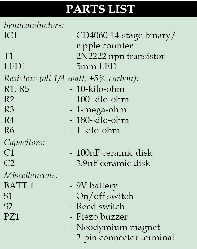
Fig. 2 shows circuit diagram of the museum watchdog. It employs a 14-stage binary/ripple counter IC CD4060 (IC1), reed switch S2 and a few other components.
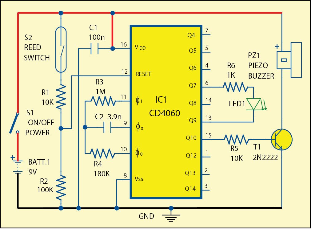
 The reed switch sensor is primarily intended to be used with a thin neodymium magnet (the strongest type of permanent magnet commercially available). The switch is fitted to the platform of the plinth, and the magnet is attached to the bottom of the object itself such that when the object is lifted, the reed switch sensor contact opens. This enables IC1 and buzzer to start beeping. At the same time LED1 starts blinking, which serves as a visual indication.
Power supply for the circuit is provided by a standard 9V battery.
Construction and testing
A single-side PCB for the museum watchdog is shown in Fig. 3 and its component layout in Fig. 4.
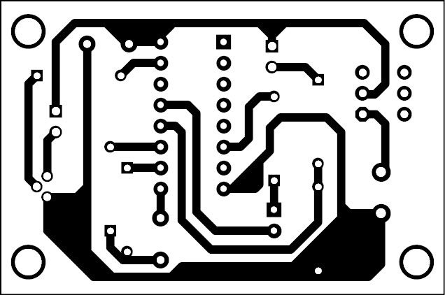
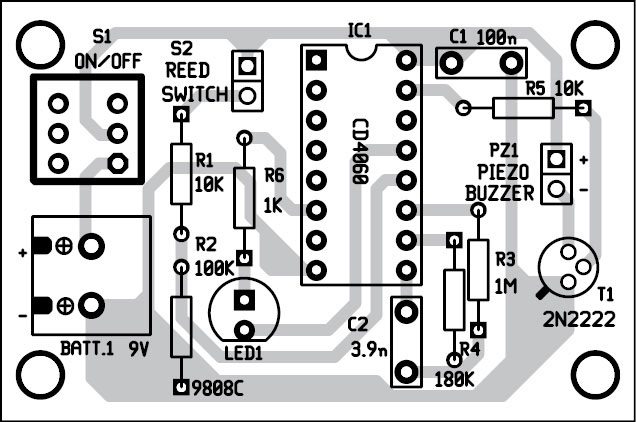
Download the PCB and component layout PDFs: click here
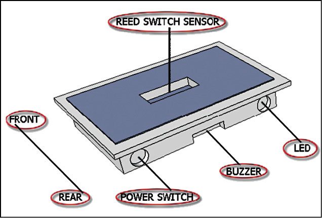
Enclose the PCB in a suitable small box and connect the reed switch externally using wires. Follow the appropriate labels for the box as shown in Fig. 5.
Place the magnet (not shown here) near the reed switch in such a way that the switch is closed/shorted, and when the magnet moves away, the switch is opened.
To make it user-friendly, it can be mounted on a plastic casing to fit comfortably in any display plinth. Some form of glue is required to hold the magnet in place. For a smaller magnet, double-sided adhesive tape can be used.
Never use a hot glue gun on a neodymium magnet as the high temperature may demagnetise the magnet.
T.K. Hareendran is an electronics hobbyist, freelance technical writer and circuit designer.

Please explain the working
Hi, all the information related to the project are already present in the article.
Please explain the working and what is the importance of ic in the circuit