
Earlier in this series, a compact FM radio was created using a touch display. From there, the design moved forward with an FM radio integrated into an earbud—though that version had a limitation: the earbud had to be reprogrammed each time the channel needed to be changed. Now, the design journey continues with a fully standalone FM earbud that no longer relies on an external MCU for channel selection or other functions.
POC Video Tutorial
Table of Contents
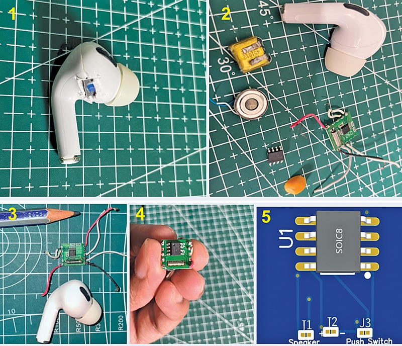
In this version, both the MCU and user interface are built entirely into the earbud itself. Fig. 1 shows the earlier prototype, a comparison of individual components (placed next to a seed for scale), and the final surface-mounted PCB.
This is the smallest working system in the series so far. That said, it does require surface-mount soldering experience. A compact MCU and single-switch interface allow users to switch FM channels (up/down) and adjust volume. The design is compact enough to fit within an earbud, but the battery capacity remains limited, restricting extended listening time. With some reconfiguration, the earbud cavity can be modified to accommodate a larger battery.

For better reception, an external or SMD antenna can also be integrated into the system. In the current version, a simple wire coil has been used inside the earbud to act as an antenna, avoiding the need for external components while keeping the design ultra-compact.
Bill of Materials
Component selection is critical, as the entire FM radio must fit inside the earbud. Ultra-compact parts are required, with the MCU and FM module being key. As in the earlier design, the RDA5807 FM module has been used, one of the smallest available. It communicates via I2C, allowing channel changes, volume control, and station scanning, all managed through an MCU.
| Bill of Materials | ||||
| Name | Designator | Footprint | Quantity | Manufacturer Part |
| 2PIN-PAD-SMD | J1, J2 | 2PIN-PAD-SMD | 2 | SMD solder pad |
| HDK-100832-011 | Speaker | Speaker | 1 | HDK-100832-011 |
| SPST slide switch | SW1 | SMD-7P, 5×1.4mm | 1 | SS-205-AGS7P-200 |
| Push button | SW2 | KEY-SMD_4P-L3.1-W3.1-P2.00-LS4.0 | 1 | TS3325A 250gf 025 |
| ATTINY412 | U1 | SOIC-8_L4.9-W3.9-P1.27-LS6.0-BL | 1 | ATTINY412-SSN |
| RDA5807 | U2 | RDA5807 | 1 | |
| 30-50 mAh Tws bud battery | J2 | SMD solder pad | 1 | EEMB LP401012, D10 Kp-581013X similar battery |
| 10µF capacitor | C1 | Through hole, D5xL11.5mm | 1 | ECR1HBK100MLL050011 |
| IC Programmer Arduino/UPDI Programmer | NA | NA | 1 | Arduino Uno |
The selection of the MCU is particularly critical. The voltage operating range of the MCU must match that of the FM module. The MCU must also provide an I2C port for communication with the FM module and consume the smallest amount of energy to maximise the runtime on a small battery. To meet these requirements, one recently released option is from Texas Instruments (TI), detailed at: click here
Another option is from Microchip’s ATtiny series, which offers SMD versions in various small packages. The WCH CH32V003 series of MCU chips can also be considered.
For ease of programming, the ATtiny412 MCU from Microchip was selected. However, other MCUs can also be used with appropriate code adjustments. The ATtiny412 requires a UPDI programmer but can also be programmed using an Arduino Uno, which many hobbyists already have.
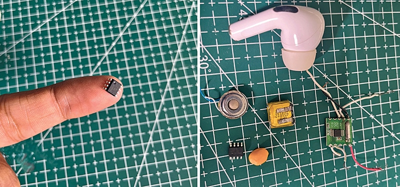
Similarly, other MCUs such as the ATtiny85 can be programmed via Arduino Uno. In this device, the Arduino Uno is used as a programmer board, not as the main MCU. Fig. 2 displays the Tiny412 MCU IC on a fingertip, alongside other components compared to a pulse seed for scale.
To assemble this device, components are listed in the Bill of Materials table.
Creating Firmware
The code has been prepared using the Arduino IDE. It is natural to wonder whether this MCU can be programmed using the IDE. The answer is yes, not just this model, but all the MCUs mentioned earlier are compatible. To keep the design as compact and simple as possible, with the battery, buttons, and PCB all fitting inside the earbud, a single pushbutton has been used to handle the entire user interface. This one switch manages scanning for stations, changing channel frequencies, adjusting volume, and play/pause control.
A common question is how all of these functions can be managed with a single switch.
The working of the switch and its function definitions in the code are explained next. Fig. 3 shows the code snippet defining button functions for the user interface (UI).
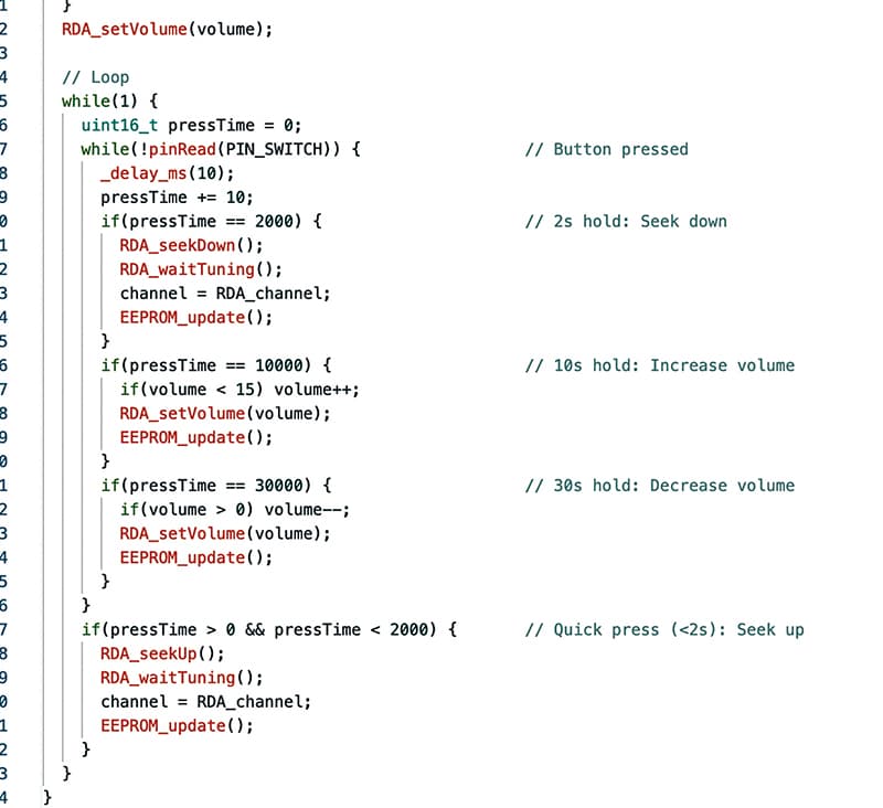
Switch Function