A high-voltage, bidirectional electronic fuse architecture demonstrating ultra-fast fault protection, low-loss SiC switching, and isolated current monitoring for 400V DC power systems up to 40 kW.
For engineers designing high-voltage power electronics, protecting DC power buses from short circuits, overloads, and inrush currents is a critical design challenge. Mechanical relays and traditional fuses often struggle to provide the fast response, reset capability, and monitoring features required in modern systems such as EV traction inverters, industrial drives, battery energy storage, and DC fast-charging infrastructure. The 400 V DC bidirectional eFuse reference design from Vishay Intertechnology offers a practical architecture that design engineers can adopt to implement fast, resettable protection in high-power DC systems.
By combining silicon carbide switching devices with isolated sensing and analog control, the design demonstrates how to build a high-efficiency electronic fuse capable of protecting loads while maintaining system reliability and reducing downtime.At the core of the reference design is a semiconductor-based eFuse capable of handling up to 400 V DC and 100 A, delivering continuous power levels of up to 40 kW. Unlike conventional fuses that permanently disconnect the circuit once triggered, the electronic fuse can be reset, enabling faster system recovery and improved maintainability in high-availability applications.
The design integrates silicon carbide (SiC) MOSFETs/JFET cascodes as the main switching elements, providing extremely low conduction losses and enabling the circuit to operate at full power with less than 30 W of losses, eliminating the need for active cooling. This makes the architecture particularly attractive for compact power electronics platforms where thermal management is a key constraint.A major advantage of the design is its ultra-fast protection capability. The system monitors current continuously and can shut down the load in less than 2.5 microseconds during an overcurrent event. Such fast response helps prevent catastrophic damage to downstream power electronics, batteries, or DC link components.
The circuit also includes a pre-charge (preload) function to safely charge DC-link capacitors when the system powers up. This controlled charging avoids high inrush currents that could otherwise stress power components or trip protection circuits.To maintain safe isolation between the high-voltage power stage and the control electronics, the design employs the VOA300 optocoupler for transferring measurement data across the isolation barrier. Analog control circuitry resides on the low-voltage side, allowing engineers to implement monitoring and protection algorithms without exposing sensitive electronics to the high-voltage domain.
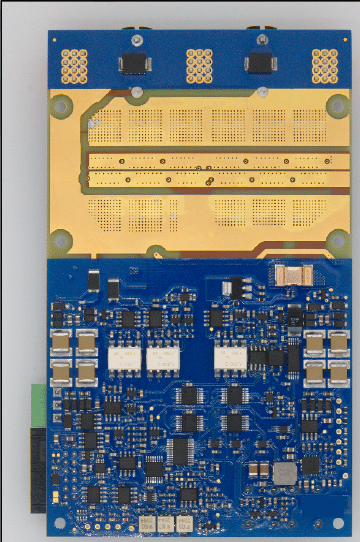
Current sensing and measurement signals can therefore be safely transmitted to the controller while maintaining system isolation requirements common in automotive and industrial standards.From a hardware perspective, the reference design is implemented on a four-layer FR4 PCB with thick copper layers to support high current flow. The board integrates the high-voltage power stage, connectors, control buttons, status LEDs, and test points on the top layer, while the low-voltage control circuitry is placed on the bottom side. Engineers can enable or disable the eFuse directly through onboard push buttons or via an external controller interface, making the design suitable both for evaluation and system integration.
Overall, this reference platform provides engineers with a validated blueprint for building fast, resettable DC protection circuits in high-power systems. By demonstrating efficient SiC switching, isolation-based sensing, and ultra-fast fault response, the design can significantly accelerate the development of robust protection architectures for next-generation electrified and high-voltage industrial applications. Vishay Intertechnology Inc.has tested this reference design. It comes with a bill of materials (BOM), schematics, assembly drawing, printed circuit board (PCB) layout, and more. The company’s website has additional data about the reference design. To read more about this reference design, click here.