

Reference design delivers a high-voltage DC output from a wide AC input range using boundary current mode control for power factor correction.
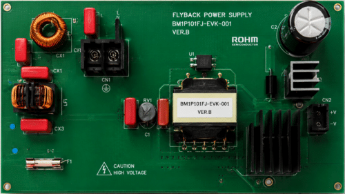
ROHM Semiconductor has developed a 200 W power factor correction reference design that converts a wide-range AC input into a high-voltage DC output. The design accepts an input voltage of 90 V to 264 V AC and provides a typical output voltage of 395 V, with an output current of up to 0.5 A. It is intended for products that require power factor correction and provides a platform for evaluating the performance of the power factor correction stage.
The reference design uses boundary current mode control in the power factor correction circuit. This control technique senses the current and manages the switching process so that the power stage operates near the boundary between continuous and discontinuous conduction. Zero-current detection controls the switching timing, helping minimise switching losses and noise.
The input frequency ranges from 47 Hz to 63 Hz, with a maximum output power of 200 W. At an input voltage of 230 V AC and an output current of 0.5 A, the design achieves a power factor of 0.97 and total harmonic distortion of 3.6 per cent. The reference design achieves a typical efficiency of 96 per cent under these conditions. The typical output ripple voltage is 11 V peak-to-peak at a 90 V AC input and 0.5 A output current, excluding spike noise.
The evaluation board provides a hold-up time of at least 20 ms while maintaining a minimum output voltage of 280 V. The operating temperature range is –10°C to 65°C. The operating time should be adjusted according to the surface temperature of the components, which should remain below 105°C during operation. These features allow the evaluation board to be tested under different input-voltage and load conditions while evaluating the operation of the power factor correction circuit.
ROHM provides supporting documentation, including a user’s guide, schematics, a bill of materials and PCB layout data. These resources enable engineers to understand the circuit configuration, evaluate its operation and modify the design for applications requiring power factor correction. The reference design provides a practical platform for developing and evaluating power factor correction circuits for power-supply applications.
For more information, click here.